

Vacuum Conditions in Water Treatment Systems: Valve Selection and Common Solutions
- 2026-09-16 09:30:53
- admin
- NO COMMENTS
A raw-water transfer pump trips during filter backwash. The motor stops, yet the water column continues down the falling main. At the nearest summit, the compound gauge drops below zero; seconds later the pipe shudders and the check valve closes with a metallic blow. On restart, operators hear gravel-like noise near the pump although the strainer is clean.
Those are familiar warning signs in water plants. Air may be trapped at a high point, the float may be sticking, or the line may be entering vacuum faster than the inlet can respond. Engineers also notice unstable differential pressure, low-flow vibration, rising actuator torque, or a damp seat. Left alone, a brief transient can become column separation, cavitation damage, pipe collapse, or a production-stopping joint leak.
How Valve Selection Helps Prevent Cavitation and Pipeline Damage in Water Treatment Systems
Introduction to Water Treatment Solutions
Overview of Water Treatment Processes
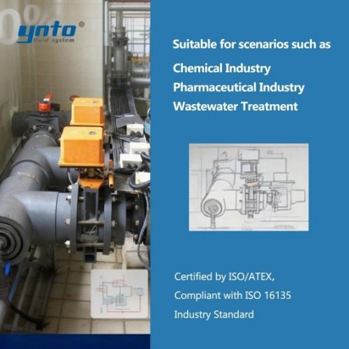
A treatment plant does not have one uniform water service. Intake lines carry grit; dosing skids handle concentrated chemicals; filters alternate between service and backwash; clear-water pumps feed long mains. Wastewater management systems add solids, biological gas, and hydrogen sulfide. Flow direction, static head, and pump duty may change several times in one cycle.
The anti-vacuum strategy must follow those changes. A valve selected from pipe diameter alone may admit too little air during drainage or expel it too aggressively during refilling, changing the pressure seen by pumps, seals, instruments, and supports.
Significance of Pipeline Infrastructure
Pipeline infrastructure stores energy. When a pump stops, the moving liquid continues, and a fast-closing valve may separate the downstream column. If local pressure falls below vapor pressure, cavities form; their later collapse pits metal and creates surge. Sustained sub-atmospheric pressure can also buckle pipe not designed for vacuum.
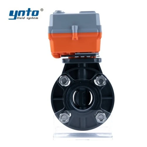
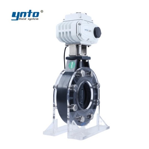
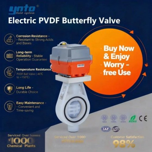
Large isolation valves influence that transient. A correctly sized electric flanged butterfly valve for water treatment can provide low-loss automated shutoff in compatible DN50-DN800 service with several seat options. Its closing time should come from a surge study. Faster is not automatically safer.
Valve Solutions for Vacuum Conditions in Fluid Transfer Systems
How Valves Help Manage Vacuum and Negative Pressure
An air/vacuum valve is open when a line is empty. During filling, its large orifice exhausts bulk air; rising liquid lifts the float and closes the outlet. If pressure later falls below atmospheric, the float drops and admits air. This limits external-to-internal differential pressure and reduces collapse or uncontrolled column separation.
During commissioning, connection size is not the decisive number. Engineers compare required inflow and outflow with capacity curves at the allowed differential pressure. They model pump trips, line breaks, rapid draining, and valve closure against allowable negative pressure. An undersized orifice opens but cannot pass enough air. An oversized outlet can discharge air so quickly that returning water strikes the closing float and causes slam.
The valve also needs clean atmospheric access. Its screened hood, vent, or chamber must not flood or block. Potable service may require sanitary approval; wastewater service may require hydrogen-sulfide vent routing and odor control instead of discharge into a confined room.
Types of Valve Solutions for Vacuum Conditions
An air-release valve uses a small orifice to vent pockets while the main remains pressurized. An air/vacuum valve uses a large orifice for bulk exhaust during filling and intake during draining. A combination valve performs both functions. Wastewater versions generally have larger passages and flushing access because clean-water mechanisms may foul in sewage.
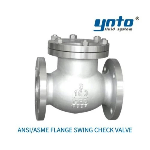
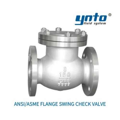
A vacuum breaker intended only to admit air is useful where exhaust is handled elsewhere. It is not a check valve. An ANSI/ASME flange swing check valve can stop reverse liquid flow after pump shutdown, but it cannot supply air to relieve negative pressure. Check-valve closure, column deceleration, and air-valve response must be assessed together.
Implications of Cavitation for Pipeline Integrity Management
Overview of the Cavitation Phenomenon
Cavitation begins when local absolute pressure falls below vapor pressure. Vapor cavities travel into higher pressure and implode. Operators describe the sound as gravel in a pump or control valve. Repeated collapse creates sharp-edged pits, unlike the broader loss of ordinary corrosion.
Anti-vacuum valves reduce one route to this condition: vacuum caused by rapid draining, pump trips, or separated columns. They do not cure cavitation from excessive throttling pressure drop, inadequate pump suction head, or a poor impeller operating point. Transient pressure data, an NPSH review, and damage location help separate the mechanisms.
Effects of Cavitation on Pipeline Systems
The damaging chain is short. A pump trips, inertia carries water beyond a summit, pressure collapses, and a vapor cavity or separated column develops. When the column rejoins, the pressure rise loads gaskets, shafts, anchors, and instruments. A flange leak may appear only after many events, so an occasional bang is not normal.
Trapped air creates another chain. The pocket reduces flow area, head loss rises, and the pump moves away from its efficient region. Energy use increases, readings fluctuate, and suction or discharge conditions may approach cavitation. Removing the air restores capacity, but it does not correct poor pump or control-valve sizing.
Enhancing Fluid Transfer Systems
Benefits of Proper Valve Selection
Good selection improves hydraulic efficiency because air no longer blocks high points, distorts meters, or adds pumping head. It protects pipeline integrity by limiting negative pressure. The objective is a controlled transient, not the largest available valve.
For an inquiry, provide the pipeline profile, diameter, material, wall class, pressure, fill and drain rates, pump curve, check-valve behavior, flow, temperature, and solids or gas content. State allowable vacuum and filling time. Those inputs define valve type, air capacity, closing behavior, and location through transient analysis.
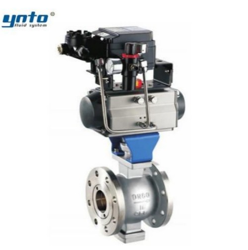
For solids-bearing wastewater modulation, a pneumatic V-type control ball valve offers a shearing V-port, but its trim and pressure drop still need erosion and cavitation checks. Material compatibility matters too. FBE-coated ductile iron is common for municipal water; 316L suits many treatment duties, while Duplex or Super Duplex may suit severe chlorides. EPDM, FKM, and PTFE each have different temperature and chemical limits. Carbon or alloy steel may require FBE or Halar protection, with coating holidays controlled.
Material selection does not stop at corrosion resistance. Low temperature changes elastomer recovery, while warm chlorinated water can accelerate swelling or hardening. Carbon steel and alloy steel bodies need a defined corrosion allowance plus coating inspection at edges, drains, and fasteners. In potable systems, elastomers, coatings, and lubricants must carry the approval required by the local authority. For hypochlorite or sludge service, actual concentration and solids data outweigh a broad material-family label.
Case Studies: Successful Implementations
Consider a filtered-water main with a summit beyond the pump station. Power loss produces negative pressure and a hard restart surge. A model shows insufficient air intake. A properly sized combination valve, coordinated check-valve closure, and slower downstream isolation keep pressure within the pipe envelope. The improvement comes from system response, not one component.
In a wastewater force main, flow loss and noise recur despite a sound pump. Inspection finds a fouled air valve and corrosive gas pocket. A sewage-service combination valve with flushing access restores air management; safe venting and service isolation reduce exposure. These are representative scenarios, not performance guarantees.
Pressure Control Valves as Complementary Solutions
Importance of Pressure Control in Water Treatment
Pressure control valves manage the positive-pressure side. They stabilize filter feed, protect equipment, or reduce high supply pressure. Poorly selected trim creates another problem: excessive differential raises jet velocity, local pressure falls below vapor pressure, and cavitation erodes the plug, cage, or downstream pipe.
Engineers often notice low-opening vibration first. The controller hunts, the plug makes repeated micro-movements, guides wear, and response slows. Oversizing is common because the valve then works close to its seat. Correct Cv, rangeability, minimum flow, staged reduction, and anti-cavitation trim matter more than line-size matching.
For suitable clean liquid service, a self-operated pressure control valve uses process pressure to position its trim and can regulate upstream or downstream pressure without external power. Confirm pressure range, materials, leakage class, and dynamic behavior. It complements an air/vacuum device; it does not replace one.
Integration with Anti-Vacuum Technology
Integration starts with one transient model containing pump inertia, check-valve dynamics, control-valve travel, actuator timing, air capacity, pipe elasticity, and elevation. It tests starts, planned stops, power loss, emergency closure, draining, and filling. Pressure valves limit positive pressure; air/vacuum valves limit negative pressure.
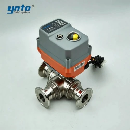
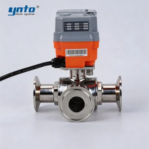
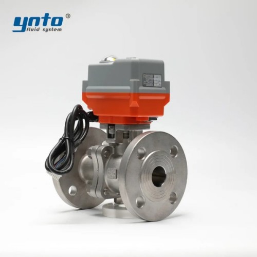
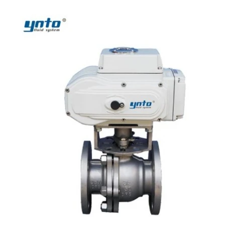
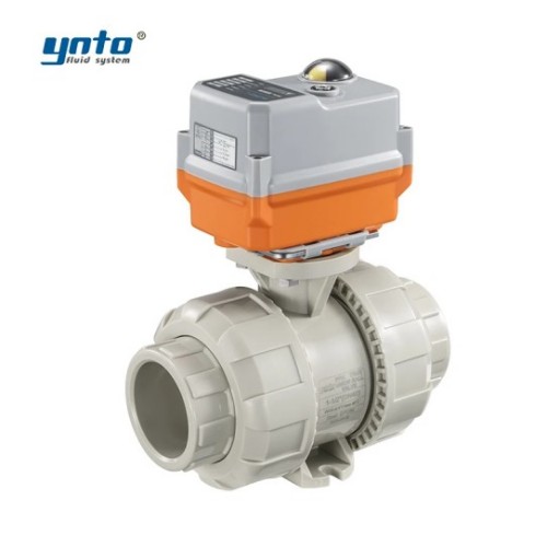
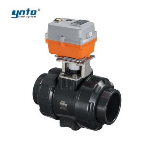
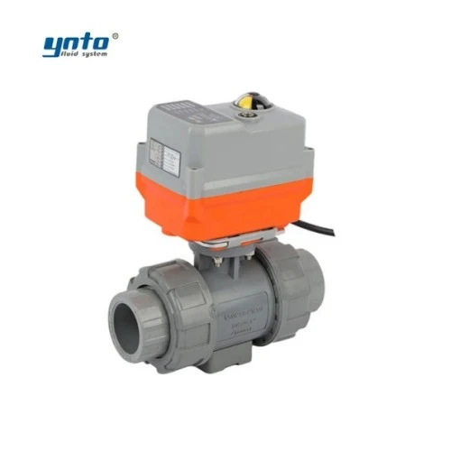
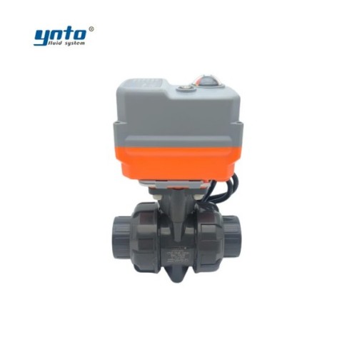
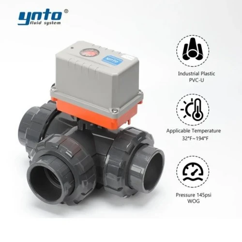
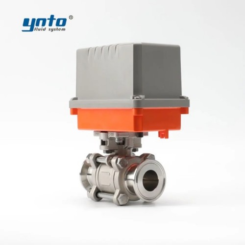
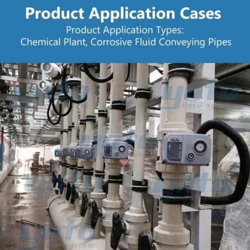
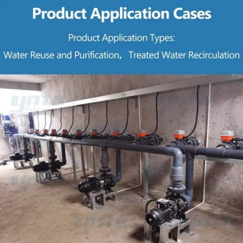
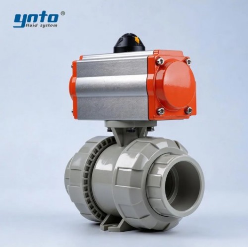
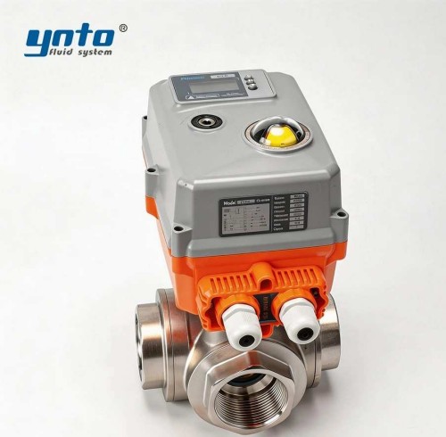
Automation adds evidence. Pressure transmitters at summits, valve-position feedback, pump status, vibration, and chamber level can be trended. An electric valve or pneumatic actuator needs an engineered stroke time and fail position. A diaphragm valve isolates its actuator from dosing chemicals; a ball valve gives branch isolation, while a butterfly valve is economical on large mains. Each solves a different problem.
Best Practices for Installation and Maintenance
Guidelines for Efficient Setup
Install air valves at high points, gradient changes, long slopes, pump discharges, downstream of fast isolation, and locations affected by draining. Final spacing follows the hydraulic profile and transient study. Keep the valve vertical unless another orientation is approved, and size the riser for design airflow.
Provide service isolation, locked or supervised open so protection is not accidentally removed. Chambers need drainage, ventilation, flood and frost protection, and working clearance. Wastewater units also need safe washdown and vent handling. Avoid restrictive fittings between the main and the air valve.
Assign standards by scope. ANSI/AWWA C512 addresses air-release, air/vacuum, and combination valves for water and wastewater. DIN EN 1074-4 covers water-supply air-valve fitness and verification tests. ASME B16.34 may govern ratings, materials, testing, and marking for applicable metal valves; ASME B16.5 covers specified flanges. API 598 and ISO 5208 provide industrial-valve inspection and pressure-test frameworks, but do not prove air capacity or surge protection. The purchase order must name editions, coating, tests, leakage acceptance, and certificates.
Routine Maintenance Considerations
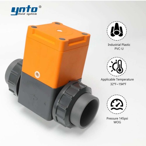
A valve can look intact and still be unavailable. Engineers check leakage, screens, float movement, vents, coating, corrosion, flooding, and service-isolation position. A corrosion-resistant UPVC diaphragm valve can control compatible chemical streams on treatment skids, but its pressure, temperature, diaphragm, and media compatibility are separate from main-line anti-vacuum duty. Wastewater solids often demand more frequent flushing than the calendar suggests.
Maintenance begins with plant lockout and confined-space rules. Isolate, depressurize, verify zero pressure, drain hazardous liquid, and control compressed air or hydrogen sulfide before opening the body. Never stand over an outlet or loosen a pressurized cover. After service, complete specified tests, reopen gradually, and record as-found condition and return-to-service readings.
Seal aging offers another causal clue. Disinfectant exposure and temperature cycling harden an incompatible elastomer; seepage starts; deposits then increase sticking. Selecting EPDM, FKM, or PTFE from actual concentration and temperature interrupts that sequence. Potable-service approval remains mandatory.
Conclusion
The Future of Pipeline Integrity Management
The next step in pipeline integrity management is better connection between transient analysis and operating data. High-speed pressure logging identifies events that create negative pressure; valve-position and pump-current trends reveal changing closure or air binding. Diagnostics then direct maintenance before surge causes damage.
Future water treatment solutions will combine sized air valves, pressure control valves, check valves, isolation, actuators, and monitoring. Digital tools improve visibility, but capacity, stable closing, suitable materials, access, and a testable maintenance plan remain fundamental.
Final Thoughts on Environmental Impact
Effective air management supports more than equipment life. Avoiding collapse and joint failure reduces water loss, wastewater discharge, excavation, and replacement materials. Removing trapped air lowers pumping head and energy use. Safe vent routing keeps corrosive gases away from people, making the station part of the plant's environmental protection equipment.
For procurement, send the medium, pipeline profile, pressure history, pump data, fill and drain cases, air-capacity requirement, materials, actuator logic, and standards. YNTO can then configure complementary control, isolation, check, diaphragm, ball, and butterfly valves around a dedicated air/vacuum solution. This protects hydraulic efficiency without claiming one valve solves every transient.
- 2026-09-14 15:59:43

- 2026-09-11 16:48:37