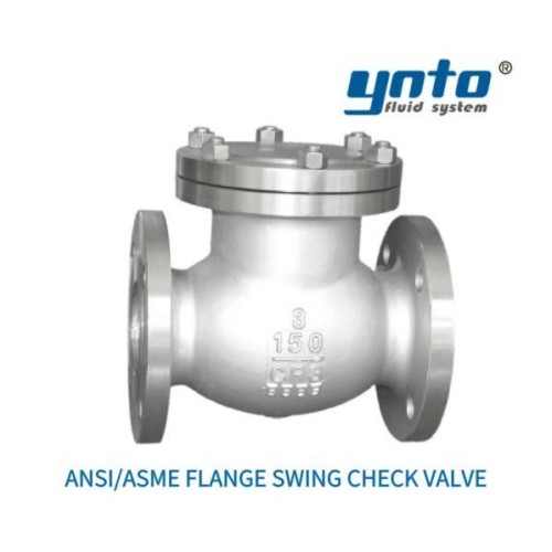
BOP Pressure Control Systems: Drilling Safety Guide
- 2026-09-23 14:43:17
- admin
- NO COMMENTS
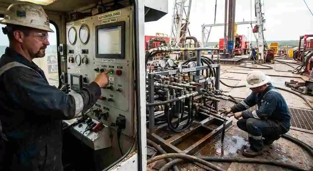
The command appears on the driller’s panel, but the hydraulic pressure trace hesitates before the selected BOP function responds. During a scheduled test, the closing unit runs longer than expected, and a technician notices a damp connection beneath the manifold. Neither observation proves that the preventer has failed. Both deserve attention before the equipment is needed under well pressure.
That is where useful engineering starts: with the gap between an instruction and a verified result. A seal may be bypassing internally, a restriction may be slowing hydraulic flow, or feedback may be reporting the wrong condition. For drilling contractors and equipment buyers, understanding these possibilities matters more than selecting the largest pressure rating on a quotation.
Understanding Pressure Control Valve Systems (BOP) for Drilling and Extraction: A Comprehensive Overview
What Are Pressure Control Valve Systems?
Definitions and Key Terminology
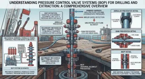
A blowout preventer, or BOP, is purpose-built equipment for containing wellbore fluids. It is not simply a pressure-reducing valve. The wider pressure-control system combines mechanical barriers, hydraulic power, controls, pressure-rated flow paths, and operating procedures. Its configuration must match the well and the drilling installation. SLB’s BOP definition describes this essential containment role.
In conventional drilling, the drilling-fluid column provides the primary pressure barrier when its hydrostatic pressure is appropriately maintained. Formation fluid entering the well is an influx, commonly called a kick. A blowout is uncontrolled flow. The distinction matters: detecting and managing an influx is not the same task as recovering a well after containment has been lost.
BOP systems provide secondary mechanical well control. They can close appropriate wellbore flow paths and support controlled circulation through dedicated equipment. They do not remove the need to understand formation pressure, casing limits, fluid properties, and barrier status.
An internal blowout preventer, or IBOP, addresses flow inside the drillstring. Annular and ram preventers address different sealing duties around tubulars or across the wellbore. These are complementary functions, not interchangeable product names. Production wellheads and trees also have distinct barrier duties; a drilling BOP should not be treated as the normal production throttling valve. SLB’s IBOP terminology identifies the internal flow path explicitly.
Components and Configuration
An annular preventer compresses an elastomeric packing element around tubulars within its qualified envelope. Pipe rams seal around specified pipe sizes; variable-bore rams accommodate a defined range. Blind rams close an unobstructed bore. Shear rams cut qualified tubulars, but cutting capability and subsequent sealing capability must be established separately. SLB’s annular BOP reference explains the packing-element mechanism.
The package also includes the closing unit, accumulators, control manifolds, connections, instrumentation, and qualified choke-and-kill equipment. Engineers review these as one system. A compatible flange or a familiar electrical connector does not establish compatible pressure, flow capacity, or emergency behavior.
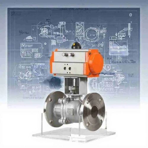
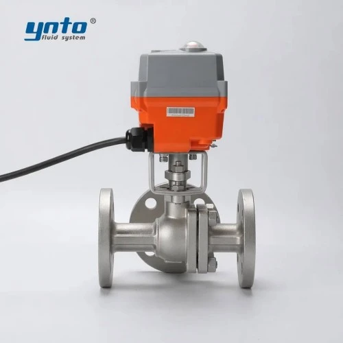
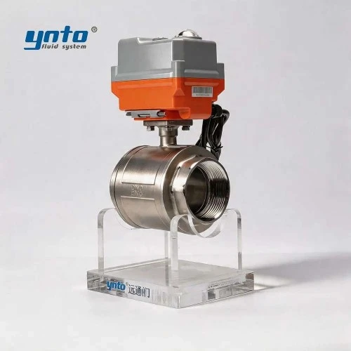
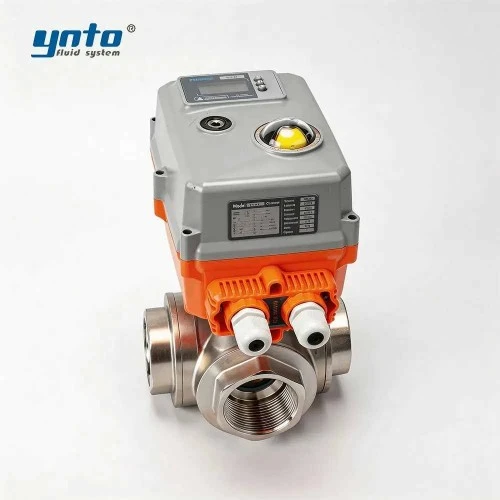
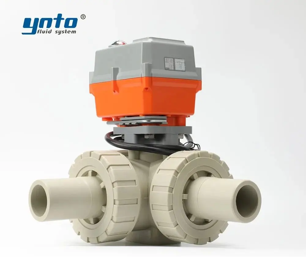
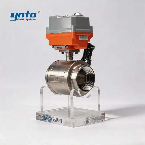
Surface utilities have a different specification. For a suitable cooling-water or clean-water branch, YNTO’s stainless steel electric flanged ball valve offers automated quarter-turn isolation with material and seat options. Its published process-valve range can support an auxiliary selection review; it does not establish BOP, drilling-choke, or high-pressure well-barrier qualification.
When comparing BOP quotations, start with the complete assembly drawing and equipment schedule. The rated working pressure must suit the specified well conditions, but bore size, temperature classification, ram compatibility, connector loads, and maintenance access can be equally decisive. Ask which components constrain the assembled system and which assumptions were used in qualification. A higher-rated preventer does not automatically upgrade connected hoses, spools, or manifold equipment. The quotation should identify included controls and interfaces clearly enough that the buyer can see where one supplier’s responsibility ends and another’s begins.
The Function of BOP in Well Control Systems
Interaction with Drilling Fluid Management
Effective drilling fluid management begins with interpreting flow, volume, density, and pressure together. Unexpected pit gain or increased return flow can indicate an influx, but transfers, equipment changes, and measurement errors also affect readings. The operating team needs calibrated instruments, clear communication, and the approved response procedure—not a diagnosis based on one moving gauge.
Fluid density is only part of the pressure picture. Circulating friction, temperature, solids loading, and pump changes influence downhole conditions. A fluid program that appears satisfactory while circulating may behave differently when pumps stop. Conversely, excessive pressure can promote formation losses, reducing the fluid column available to maintain control. More mud weight is not automatically a safer answer.
During controlled well-control operations, a dedicated drilling choke manages backpressure within the approved circulation method. Gas expansion and abrasive solids make this a demanding duty. A general-purpose control valve may offer attractive positioning accuracy yet lack the erosion resistance, qualification, or pressure envelope required for a choke manifold.
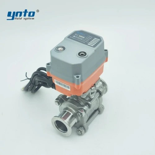
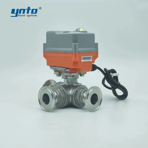
Procurement should therefore distinguish between the well-control flow path and fluid-preparation utilities. The choke-and-kill package requires its own documented design basis. Water conditioning, compatible chemical transfer, and washdown branches can use separately selected industrial valves without being represented as well barriers.
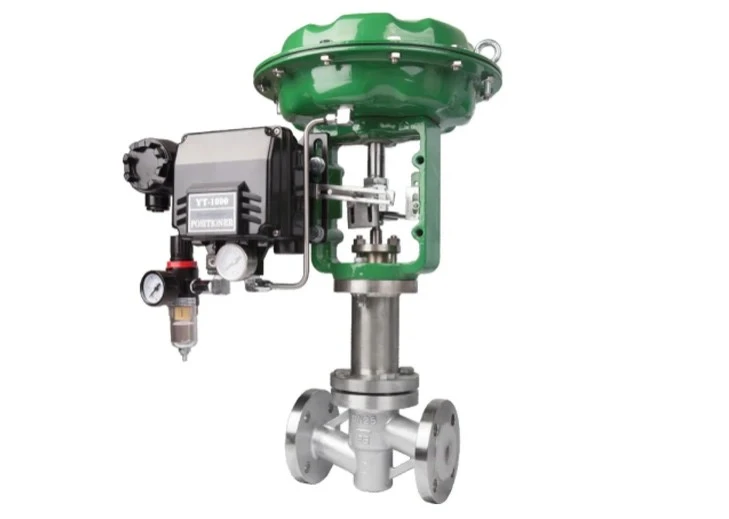
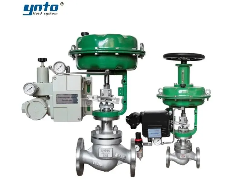
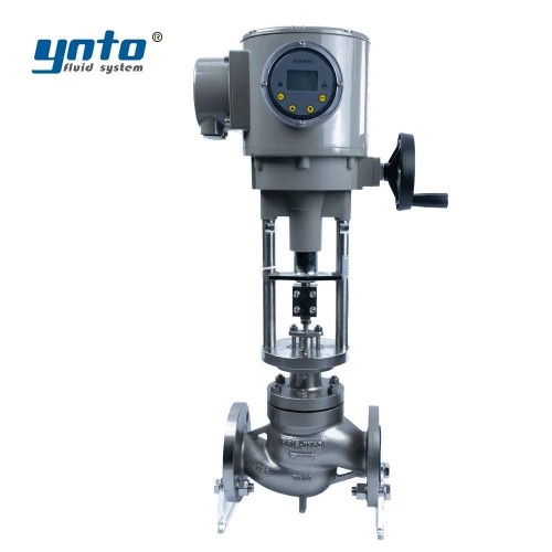
On a separate fluid-conditioning skid, persistent low-flow oscillation may point to an oversized regulating valve operating close to its seat. A small movement then produces a large flow change, the controller reverses direction, and repeated corrections accelerate wear. The engineering response is to review the operating range, available differential pressure, and valve characteristic before changing tuning. Isolation and modulation are different duties: a ball valve selected for tight shutoff should not automatically become the skid’s precision flow-control element.
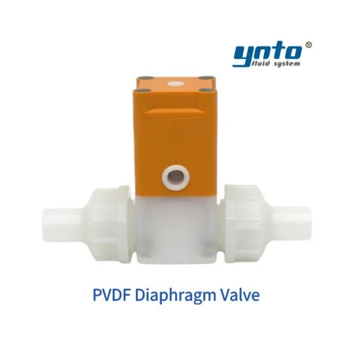
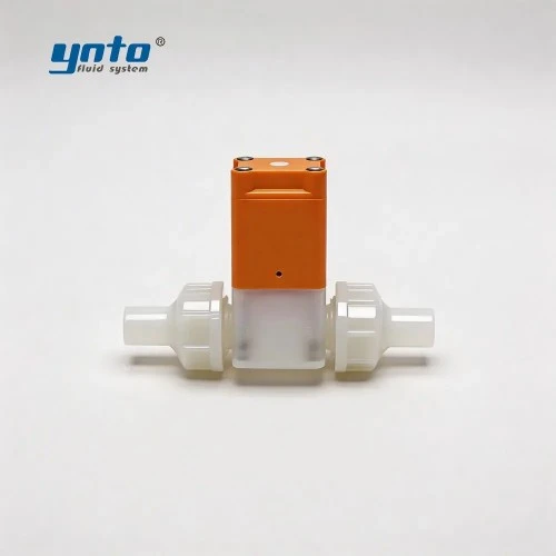
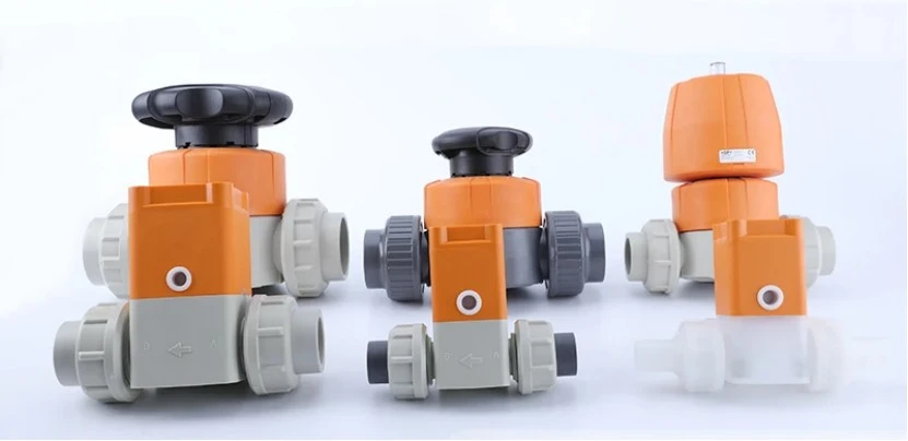
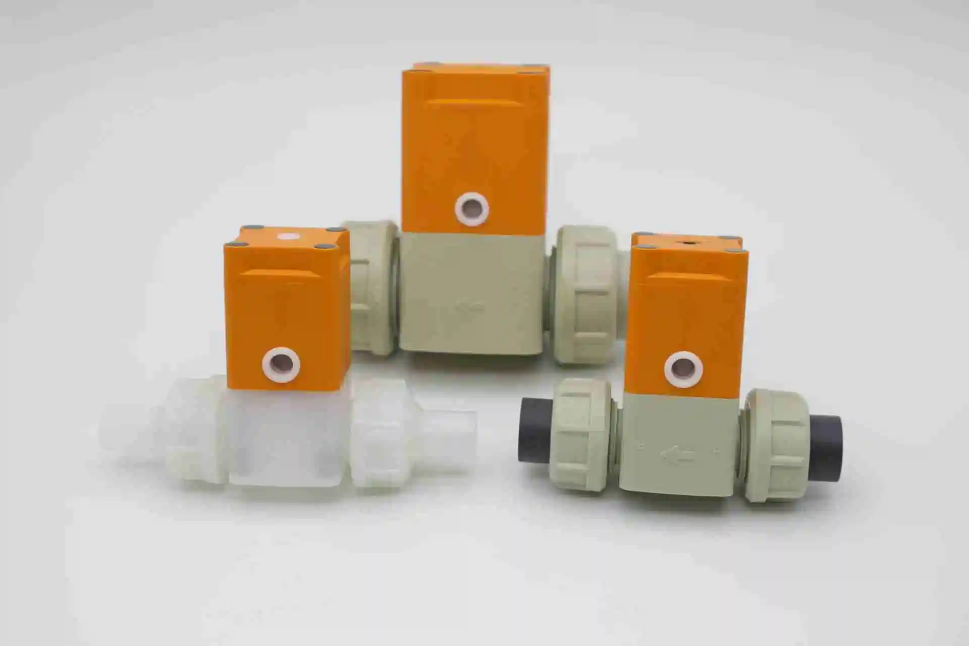
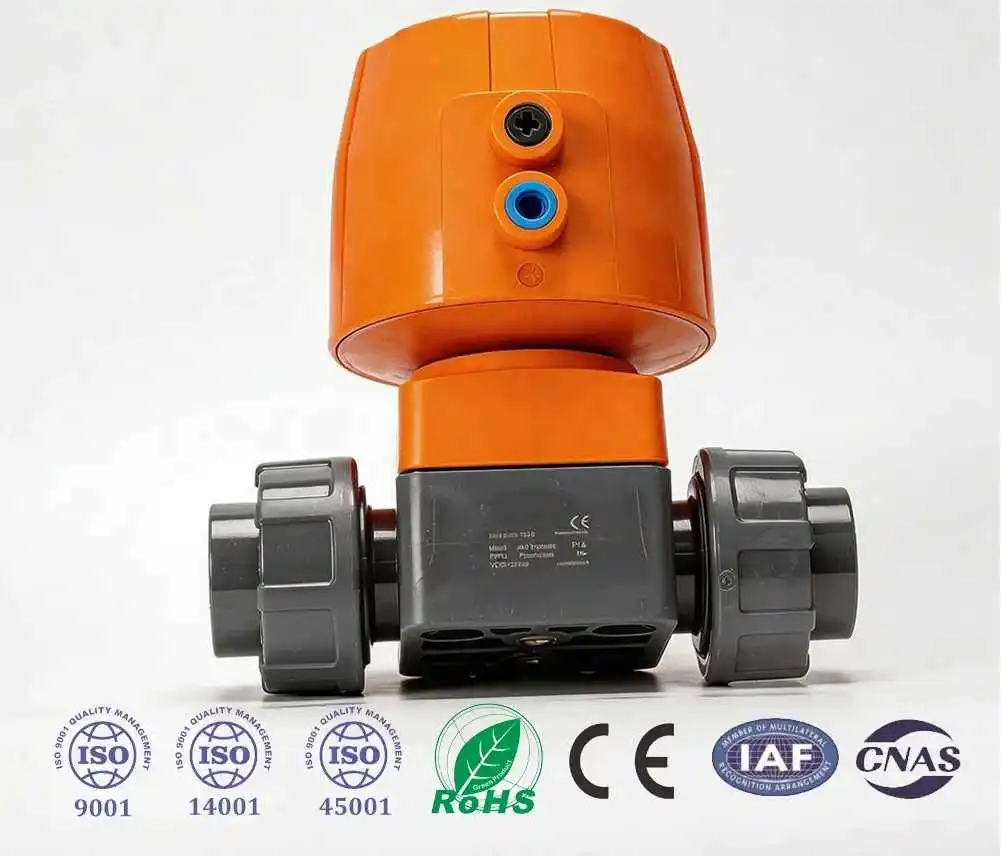
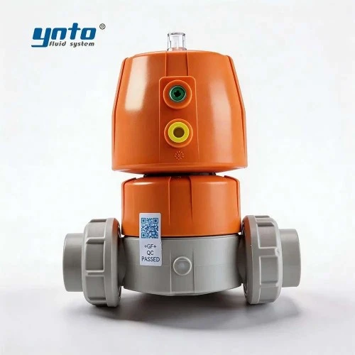
For example, the PVDF diaphragm valve listed by YNTO is a candidate for an isolated, compatible chemical-treatment or water-treatment branch. The diaphragm separates the fluid from the operating mechanism, while PVDF provides chemical resistance within its approved service limits. Confirm concentration, temperature derating, diaphragm material, and pressure rating; this is not a recommendation for the high-pressure mud circuit.
Role in Emergency Situations
When primary pressure control becomes inadequate, the BOP system provides mechanical containment options. Which function is appropriate depends on the tubular position, stack configuration, well conditions, and approved well-control program. This overview is not an operating sequence: emergency actions require trained personnel following the rig-specific and well-specific procedures.
Shear capability deserves particular scrutiny during equipment selection. Pipe body, tool joints, control lines, tubular strength, and pressure loading do not present the same cutting problem. A statement that a ram "can shear drillpipe" is incomplete without the tested envelope and evidence that the intended configuration can also seal where required.
For U.S. offshore applications, the current federal requirements address ram capabilities, redundant controls, accumulator capacity, and subsea intervention functions. Buyers must verify the applicable provisions and incorporated standard editions for their operation. A general brochure cannot replace that review. Current BOP system requirements provide the jurisdiction-specific reference.
Hydraulic Control Systems in Detail
Types and Mechanisms
Hydraulic control systems convert an operating command into force and movement. Pumps charge the system; accumulators store usable hydraulic energy; directional valves route fluid; regulators establish the required control pressures. The operating cylinders then move rams or compress an annular element. Wellbore pressure and hydraulic operating pressure belong to different circuits and must never be confused.
A surface installation may use direct hydraulic connections between the control unit and preventers. Subsea arrangements can use hydraulic pilot signals or multiplexed electro-hydraulic controls. In a multiplex system, electrical commands operate local control functions while hydraulic energy performs the mechanical work. Signal transmission alone does not supply the closing force. Wingoil’s control-system overview describes these system categories.
An accumulator bank must deliver the required usable fluid volume at adequate pressure through the relevant operating sequence. Nominal bottle volume is not the same as available operating volume. Minimum temperature, ambient pressure, hydraulic losses, and required reserve affect the calculation. These are OEM and system-design inputs, not settings to copy from another rig.
During commissioning, a useful question is whether pressure remains adequate while the function moves. A satisfactory static gauge reading can coexist with restricted flow, an undersized passage, or an abnormal return-path restriction. Record pressure, response time, and fluid use together under the specified test conditions.
Human factors belong in the design review, including abnormal operating conditions. Panel labels should match approved schematics, alarm messages should identify the affected function, and maintenance overrides should be controlled and visible. During a busy shift, an ambiguous indication can consume the response time that a faster hydraulic component was intended to save. Acceptance should therefore include the operator interface, not just the equipment hidden behind the panel.
Integration with BOP Systems
Small contamination problems can create a large response problem. Particles entering a precision valve can obstruct movement or abrade its internal surfaces. That damage can increase internal leakage, consume hydraulic supply, and make a previously repeatable function slower. The likely engineering consequence is reduced operating margin, even before a visible external leak appears. Parker’s hydraulic filtration handbook explains the underlying contamination and wear mechanisms.
The distinction between pneumatic and hydraulic pilots also matters when ordering spares. YNTO’s KG800-S stainless steel solenoid valve uses a NAMUR-style interface for compatible pneumatic actuator arrangements. It can be evaluated for an auxiliary topside air-operated valve package. It is not a substitute for a qualified BOP hydraulic control valve merely because both devices receive an electrical command.
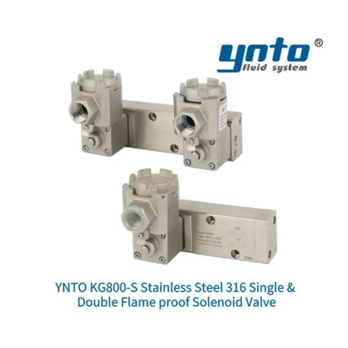
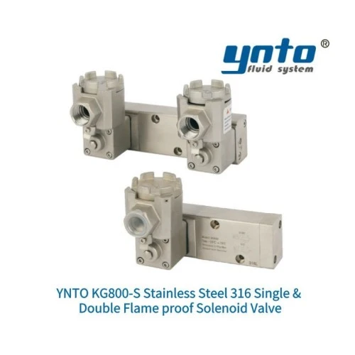
For that auxiliary application, verify the exact port arrangement, coil supply, minimum air pressure, exhaust behavior, and environmental certification. A flameproof description does not, by itself, establish acceptance for every hazardous location or a safety-integrity requirement.
Integration testing should follow the complete command path. Engineers need to understand what happens when power, communications, or one supply path is unavailable, and whether another function creates a common dependency. Two panels connected to the same vulnerable supply do not necessarily provide independent protection. Configuration changes require documented review and revalidation under the approved testing plan.
Keep the as-found condition in the maintenance record. If a technician adjusts a regulator or replaces a pilot before documenting the pressure trace, the team may lose the evidence needed to distinguish the original fault from a temporary improvement. Recording the affected function, environmental conditions, supply state, and component identity makes subsequent engineering review more useful. Spare assemblies should have controlled part numbers and revision status; physical interchangeability alone is not sufficient evidence that an alternative has the same operating behavior.
Drilling Safety Equipment and Operational Protocols
Importance of Drilling Safety Equipment
Reliable drilling safety equipment combines suitable design with maintained evidence of condition. A pressure test assesses containment under specified conditions; a function test demonstrates movement and control response. Neither alone proves every required capability. Inspection records should connect equipment identity, maintenance history, test configuration, measured results, and the person authorizing return to service.
Standards assign different responsibilities. API 16A covers drill-through equipment, API 16C covers choke-and-kill equipment, and API 16D addresses control systems for drilling well-control and diverter equipment. API Standard 53 addresses installation and testing of drilling well-control equipment systems. The purchase specification must identify the required editions, addenda, and acceptance evidence, rather than requesting an undefined “API valve.” API’s standards catalog distinguishes these scopes.
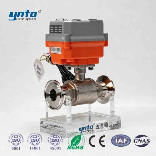
Auxiliary metal valves may instead be specified using ANSI/ASME conventions, with ASME B16.34 covering applicable pressure-temperature ratings, materials, examination, and testing. ISO 5208 addresses pressure testing of metallic industrial valves. DIN EN 558 concerns face-to-face and centre-to-face dimensions of flanged metal valves. Those requirements help define a process-valve purchase; none independently qualifies a valve as a BOP component. See the official ASME B16.34 scope and ISO 5208 scope.
Material selection must follow the actual exposure. A qualified alloy-steel pressure body needs the required strength, toughness, manufacturing controls, and traceability. In compatible auxiliary services, 316L or Duplex stainless steel may address corrosion concerns, but chloride concentration and temperature still matter. Where sour-service requirements apply, NACE MR0175/ISO 15156 guides selection against specified H2S-related cracking risks; it is not a universal corrosion guarantee. NEN’s ISO 15156 overview states that materials scope.
PTFE, EPDM, and FKM likewise describe material families, not universal seal solutions. Compound compatibility depends on the fluid and temperature, while high-pressure gas exposure can introduce decompression risks. BOP packing elements require OEM-qualified compounds. Repeated thermal cycling can reduce an unsuitable seal’s resilience; contact pressure then changes, leakage develops, and maintenance demand rises. Replacing it with the same unqualified material simply restarts the problem.
Before intrusive work, personnel must follow the facility’s barrier, permit, isolation, and lockout requirements. Isolating an electrical supply does not remove stored hydraulic energy or trapped well pressure. Hot surfaces, injection injuries, toxic fluids, and unexpected actuator movement remain credible hazards until the approved verification process establishes a safe condition.
Emergency Shut-Off Valves as Critical Components
Emergency shut-off valves isolate defined process or utility hazards. A BOP performs a different well-control role. Both may be commanded during an emergency, but their initiating conditions, closure behavior, pressure duty, and acceptance tests belong in separate, coordinated specifications.
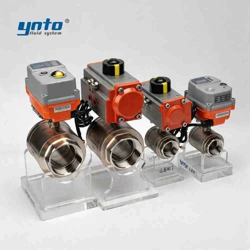
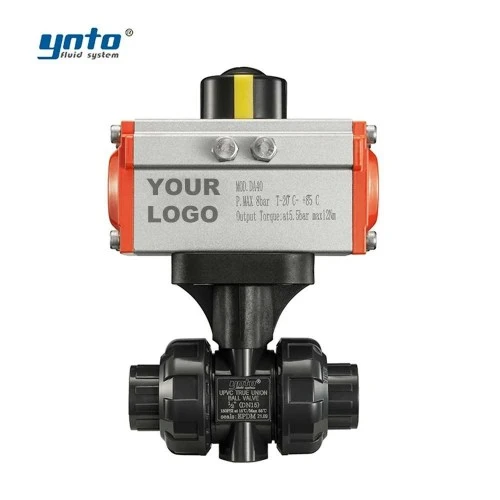
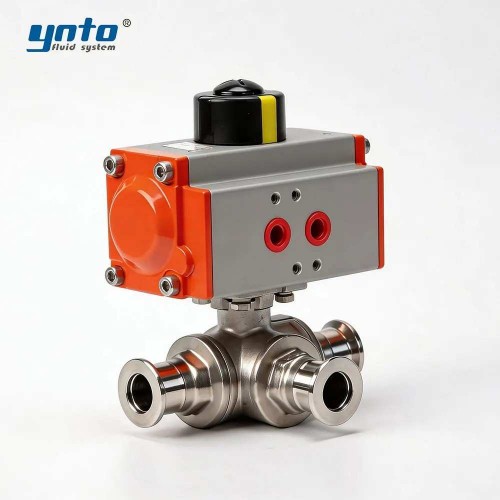
For a reviewed surface process or utility isolation duty, YNTO’s pneumatic flanged quarter-turn ball valve provides a starting point for an actuator-and-valve package. Its published options include different materials and seats. Safety-critical shutdown use would still require evidence for the complete assembly’s leakage, torque, fail action, fire performance, and functional-safety requirements where applicable. The product listing alone does not establish those qualifications.
“Fail closed” is a design requirement that must be demonstrated under specified conditions. A spring-return actuator still needs sufficient torque against differential pressure and friction. Corrosion at an exposed stem can roughen the sliding surface, damage packing, and increase resistance; the resulting demand may erode the actuator’s original margin. For engineers reviewing a shutdown package, the worst credible torque matters more than an unloaded workshop stroke.
Closure speed needs equal care. Faster isolation can reduce release duration, yet excessively rapid closure of a liquid line can generate surge. The selected timing must satisfy both the hazard analysis and the hydraulic assessment. Neither a larger actuator nor a faster solenoid automatically produces a safer installation.
Factory acceptance testing should examine the supplied assembly, including its actuator, pilot, accessories, and feedback, against the agreed specification. Once installed, site acceptance must address the actual interfaces and utilities. A successful shop test with generous air pressure does not answer whether the valve will complete its required movement at the minimum available site pressure. Similarly, a closed-position indication cannot substitute for the specified leakage test. For buyers comparing emergency isolation valve packages, these acceptance details often reveal more about suitability than the catalog’s headline operating speed.
Innovations and Technology in BOP Systems
Advances in Offshore Drilling Operations
Offshore drilling operations make access, diagnostics, and maintainability especially important. Subsea temperature, external hydrostatic pressure, long communication paths, and intervention logistics all influence the control-system design. A fault that is straightforward to repair on a land rig can require a much more demanding offshore intervention.
Current developments include modular control equipment, retrievable components, improved instrumentation, and better diagnostic interfaces. Cameron describes modular BOP control systems and retrievable multiplex control pods intended to simplify maintenance. These features are useful because they address access and serviceability, not because additional electronics inherently eliminate mechanical failure. Cameron’s BOP control-system portfolio documents these design approaches.
Emergency disconnect, deadman, autoshear, and remotely operated vehicle intervention functions have distinct purposes and initiating conditions. Their availability depends on the system and regulatory requirements. Engineers should examine the defined emergency logic, energy sources, and shared failure points instead of assuming that every subsea stack has identical automatic protection.
Historical investigations also show why qualification must reflect credible loading. The National Academies’ Macondo analysis examined how pipe position and loading complicated shear-and-seal performance. The practical lesson is not that a modern ram will necessarily repeat that failure; it is that nominal cutting capacity cannot describe every emergency condition. The BOP investigation chapter explains the mechanical limitations observed in that event.
Future of Drilling Performance Optimization
Useful drilling performance optimization improves readiness as well as uptime. Trend data can help distinguish a hydraulic restriction from changing mechanical resistance, provided the records include comparable operating conditions. A longer response at lower ambient temperature should not be interpreted in the same way as an unexplained deterioration under otherwise unchanged conditions.
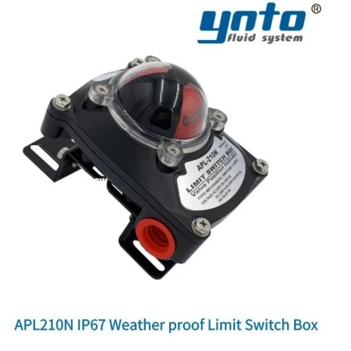
On auxiliary rotary valves, YNTO’s APL210N valve-position limit switch box provides open/closed indication for compatible installations. That feedback can improve visibility of surface utility-valve status. Its IP67 weatherproof designation does not establish explosion protection or subsea suitability, and a position signal does not prove pressure-tight sealing. The installation must match the actual location and required certification.
Digital monitoring becomes more valuable when it supports a specific maintenance decision: investigate increasing fluid consumption, check a drifting sensor, or examine a recurring difference between commanded and observed response. Alarm limits should be based on the qualified equipment and operating context. Remote dashboards must not replace local safety functions or authorize unreviewed changes to control logic.
Procurement can support this approach by requesting accessible test records, configuration backups, replacement-part identification, and documented service support. A component that is easy to order but impossible to trace becomes expensive when the crew cannot establish whether it is approved for the installed configuration.
Conclusion
Summary of Importance
BOP pressure control systems protect drilling operations through coordinated barriers, reliable hydraulic energy, qualified equipment, and competent operating practices. Their effectiveness depends on the entire system, including the conditions under which it must close, contain pressure, and support recovery of well control.
A slow function, rising fluid demand, or small leak is therefore more than a maintenance inconvenience. It is information about the available operating margin. Investigating those changes while the equipment is accessible is a practical contribution to safety, environmental protection, and predictable drilling schedules.
Call to Action for Best Practices
For BOP procurement, work with a qualified well-control equipment supplier and require documented pressure ratings, ram capabilities, control-system compatibility, and applicable test evidence. Have the project’s well-control authority approve the final package.
For auxiliary surface valves, send YNTO the medium, normal and upset pressures, temperature range, connection standard, operating frequency, actuator supply, required fail action, and area classification. Request the exact model datasheet, material specification, assembly drawing, and acceptance-test proposal. Keeping those requirements explicit helps the supplier recommend a suitable electric, pneumatic, or diaphragm-valve solution while preserving the boundary between industrial process equipment and qualified well-control barriers.

- 2026-09-21 15:23:44
- 2026-09-18 09:42:46