

CDU Coolant Dosing Valves: Seal Fit and Fail Position
- 2026-11-20 08:39
- admin
- NO COMMENTS
The CDU is holding supply temperature, but a technician notices a damp ring beneath the chemical-injection skid. The dosing pump pulses normally. Its discharge gauge, however, jumps higher than it did at commissioning, and the isolation valve takes an extra second to close. A few drops seem minor until they reach a cable tray or a sensor reports a falling reservoir level.
Replacing the valve by nominal size is tempting. Is the leak at a union, stem, or seat? Has an inhibitor changed the seal? When power fails, should this valve stop injection or preserve coolant flow? Those duties require different responses. Start with the fluid path and failure sequence, then check materials, fit, and actuator behavior.
Overview of CDU Coolant Dosing Systems in Data Center Infrastructure
Components of Coolant Dosing Systems
A coolant distribution unit (CDU) commonly separates facility water from the technology cooling loop through a heat exchanger. Pumps, strainers, instruments, and valves serve the secondary loop. A dosing assembly may include a day tank, metering pump, back-pressure device, relief return, injection check valve, and isolation. The pump meters chemical; an ordinary on-off ball valve does not.
Functionality in Data Center Infrastructure
In a live data center, cooling must continue at the required flow and temperature while dosing changes mode. The injection shutoff should stop chemical migration without blocking main circulation. Trace the P&ID from tank to injection point and across the exchanger, noting check valves and trapped-liquid volumes.
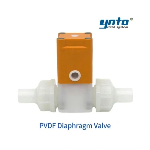
A valve near the day tank sees concentrate; one downstream of injection sees diluted coolant. The facility-water side has yet another chemistry. For corrosive additive isolation, YNTO's PVDF diaphragm valve separates fluid from the operating mechanism. Request the exact diaphragm, connection, pressure-temperature rating, and leak-test record. A catalogue description cannot establish compatibility with every biocide.
Evaluating Seal Fit in CDU Valves
Common Types of Seals Used
Seal selection starts with the fluid recipe. EPDM suits many treated-water and glycol duties, subject to inhibitor compatibility. PTFE resists many chemicals, though seat creep matters. FKM suits selected chemicals but not every glycol formulation. Compare immersion and compression-set data at normal and upset temperatures.
Body material follows the fluid. 316L can serve compatible water circuits, but chlorides and crevices need review. PVDF may suit a corrosive concentrate. Coated carbon steel can fit some facility-side circuits, although damaged coating invites corrosion. The side of the heat exchanger matters more than a “data-center grade” label.
Effects of Poor Seal Fit
A new gasket can leak if it is too thin for its groove or the ends are misaligned. Thermal cycling changes compression; the seat bypasses; chemical balance drifts. An unexplained change in makeup volume may appear before a puddle.
Measure pipe ends, face-to-face length, flange or union geometry, and actuator clearance. Check static pressure and pump-start transients. A stamped pressure class does not establish the assembly's rating at maximum fluid temperature. Do not hang unsupported pipe from a plastic body or clamp connection.
Maintenance Tips for Ensuring Proper Fit
Before opening, follow the approved method of procedure: isolate, lock out, depressurize, drain, contain, and verify no backfeed. Protect electrical equipment below. Concentrated biocide or oxidant creates splash and disposal risks even on a low-pressure line.
Clean grooves and sealing faces. Replace seals by part number and material, not apparent diameter. Support the pipe, tighten as specified, and pressure-test at the agreed medium and duration. Record baseline stroke time and leakage.
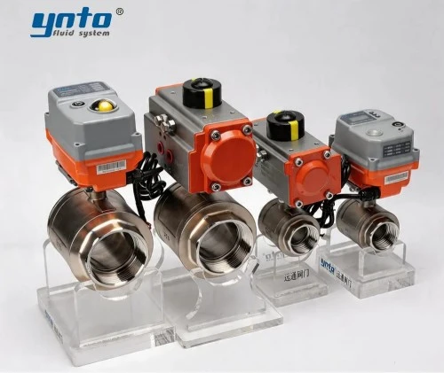
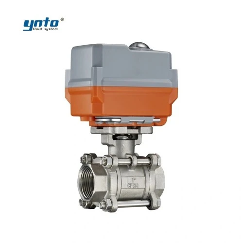
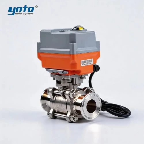
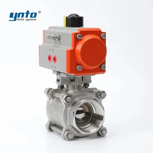
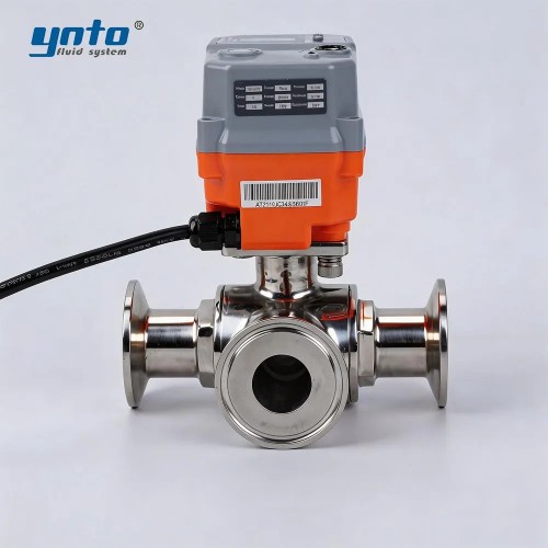
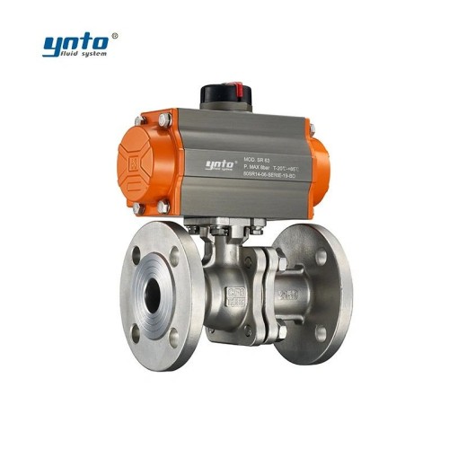
For metal-body isolation, YNTO's three-piece stainless steel electric ball valve is worth comparing. Its removable body may simplify seat inspection. Confirm the actual wetted grade, seat, ends, voltage, and pressure rating; product-family variants are not interchangeable.
Analyzing Fail Positions in Data Center Cooling Systems
Types of Fail Positions in CDU Valves
“Fail open” and “fail closed” require a named failure: mains power, control voltage, communication, instrument air, or detected leak. A normal electric actuator may hold position on power loss. A spring-return or stored-energy unit can move, but torque and return time need confirmation at maximum differential pressure.
On a chemical-feed isolation valve, fail closed may limit uncontrolled dosing if the metering pump also stops. On a three-way coolant bypass, the safe position might preserve flow through a heat exchanger or maintain a bypass until backup cooling is ready.
Consequences on System Performance
Imagine the dosing valve closes correctly on a leak alarm while the injection pump continues running. Discharge pressure rises, the pump relief path opens, and concentrate may return to its tank or another approved containment point. If that path is blocked, the valve's correct fail position does not make the skid safe. Tie pump shutdown, valve command, pressure alarm, and injection-check performance into one cause-and-effect matrix.
The main coolant circuit has the opposite risk. A close command that interrupts the only available flow path can raise cold-plate temperatures within the system's ride-through time. Test the alarm sequence with the approved redundant path in service. Confirm pump differential pressure and return temperature, not merely actuator position; a limit switch proves travel, not adequate cooling.
Implications for Data Center Sustainability
Leak-free routing and stable treatment can reduce rejected coolant, refill water, and unplanned flushing. It does not follow that any particular valve saves a fixed percentage of water or energy. Data center sustainability needs measured evidence: makeup volume, coolant disposal, pump energy, heat-exchanger performance, and avoided incidents over a comparable operating period.
Leak Detection Methods for Data Centers
Technologies for Monitoring Leaks
Leak detection methods should combine direct and indirect evidence. A rope sensor under a CDU or beneath a vulnerable connection can detect escaped conductive coolant. Reservoir-level trends, flow imbalance, and unexplained pressure decay can identify a loss that a point sensor misses. Each method has blind spots: a sensor behind the leak cannot see fluid flowing elsewhere, and a pressure trend can change for ordinary load reasons.
Place detection at credible pooling locations and test with the actual coolant or an approved surrogate. Conductivity changes as glycol, deionized water, or additive concentration changes, so the sensing threshold needs verification. Keep drip trays accessible and route alarms to the building management or data center infrastructure monitoring system with an unambiguous location label.
Role of Automation in Leak Detection
An alarm is useful only when its response is defined. A first threshold may call for inspection; a confirmed leak may stop chemical injection and isolate its branch; a major loss may require pump and IT-load coordination under the site's emergency plan. Distinguish the injection-line response from the main-cooling-loop response. Automatic closure can contain a chemical leak yet remove essential cooling if applied to the wrong valve.
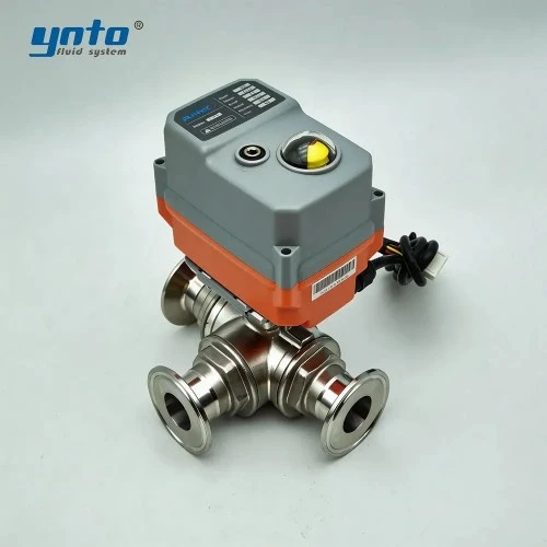
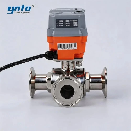
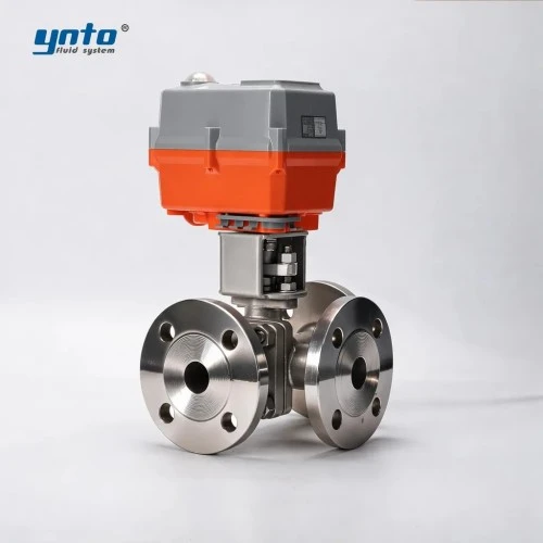
YNTO's electric three-way stainless steel ball valve lists a configurable power-off return option. Specify the actual actuator module and port map; verify the final flow path during a witnessed power-loss test rather than relying on the words “fail-safe.”
Case Studies on Effective Leak Management
Consider two illustrative commissioning scenarios, not reported site results. A union on the additive skid weeps after temperature cycling. The rope sensor alarms, the dosing pump stops, and the branch valve closes while coolant circulates. The team finds an undersized seal and retests the joint and alarm-to-valve sequence.
In the second, a three-way bypass actuator reaches its intended position, but the port orientation opposes the P&ID. A power-loss simulation diverts flow from the exchanger. The team corrects the port map and retests flow and temperature. Actuator travel alone had not proved a safe path.
Coolant Management Solutions and Strategies
Techniques for Effective Coolant Management
Good coolant management solutions begin with water-quality limits from the CDU and IT-equipment suppliers: glycol concentration where used, pH, conductivity, corrosion inhibitor, particles, and microbial control. Sampling from a convenient but stagnant branch can misrepresent the circulating fluid. Track additive batches and compare trend changes with makeup-water and filter-service events.
Integration with Cooling System Upgrades
Cooling system upgrades often alter flow, pressure, and piping access. A larger rack population may increase design flow while an added heat exchanger changes the available differential pressure. Reuse the old valve only after recalculating its capacity and reviewing the new control sequence. A replacement that fits between flanges may still lack the authority or cycling endurance required at minimum load.
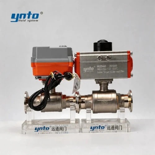
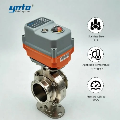
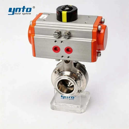
On an appropriately sized clean-coolant header, YNTO's pneumatic sanitary stainless steel butterfly valve is a connection and automation option to review. Its clamp interface is meaningful only if the existing tube, ferrules, gasket profile, pressure rating, and maintenance access match. Obtain a drawing and the exact 316L, seat, and actuator configuration; its catalogue emphasis on liquid cooling does not prove compatibility with every CDU coolant.
Smart Technologies in Coolant Monitoring
Trending stroke time, motor current or air consumption, differential pressure, and closed-valve leakage indication can direct maintenance before a fault spreads. An increase in torque after a treatment change suggests seal swelling or deposits; a pressure drop that rises while valve travel stays normal points instead toward a filter or exchanger restriction. Correlate those signals rather than replacing a healthy valve.
Standards answer separate questions. ANSI/ASME B16.34 addresses ratings and construction for applicable metal valves; API 598 and ISO 5208 frame specified shell and seat tests. ISO 5211 covers part-turn actuator attachment dimensions, not torque adequacy. DIN EN 558 guides face-to-face dimensions for applicable flanged metal valves. State editions, leakage acceptance, and connection drawings; none establishes coolant compatibility or fail position.
Preventive Maintenance Practices for CDU Valves
Regular Inspection Schedule
Set inspection frequency from the facility risk assessment, valve cycle count, treatment-chemical history, and accessibility. A dosing valve beside a live electrical cabinet deserves more frequent visual and sensor checks than an isolated utility branch. Compare each round's joint condition, actuator response, local drip-tray status, and reservoir trends with the commissioning baseline.
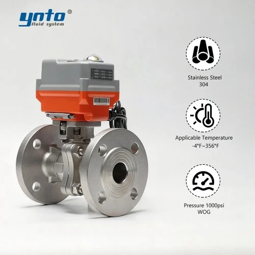
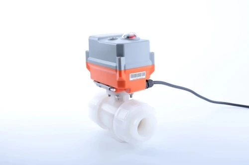
For an aggressive additive branch that needs remote isolation, YNTO's electric PVDF ball valve offers another construction to compare. Confirm whether the quoted version really has the union ends shown, which seals are supplied, its pressure-temperature derating, and its power-loss action. A ball valve may isolate the branch, but the metering pump remains responsible for dosing accuracy.
Training Staff in Maintenance Practices
Technicians should recognize the difference between a dosing failure, a coolant leak, and a cooling-capacity alarm. Practice isolating the chemical branch without accidentally closing the rack supply. Post the approved valve tags and fail positions at the skid, and include containment, depressurization, and electrical protection in the work instruction.
When a valve is replaced, demonstrate the new controller command and the loss-of-power behavior with operations present. Verify the alarm reaches the intended team and that the local manual override cannot leave an unrecorded unsafe path. A good maintenance procedure ends with an observed cooling response, not just a signed valve checklist.
Evaluating System Performance Over Time
Before and after a retrofit, compare stable-load supply and return temperature, pump differential pressure, chemical consumption, coolant makeup, leak alarms, and valve travel under similar IT loads. These measurements separate genuine improvement from a seasonal change or a revised operating setpoint. If seals fail repeatedly, send the supplier the failed part and the actual chemical formulation rather than ordering the same material again.
Conclusion
Key Takeaways
A CDU dosing-valve retrofit needs a compatible seal and a fail position suited to its hazard. Trace injection separately from cooling, size for actual pressure and flow, and test leak and power-loss responses. YNTO can quote a diaphragm, ball, or butterfly assembly against a service datasheet; obtain configuration-specific ratings and functional evidence.
Future of CDU Valve Technologies
More CDUs will expose valve travel, pressure, flow, and leak status to facility monitoring. The most useful advance will be a traceable response: the system detects an abnormal condition, closes only the appropriate branch, and shows that required cooling continues. That is a better purchasing requirement than a broad promise of a “smart” or “fail-safe” valve.
- 2026-11-20 08:39
- 2026-11-18 08:56
- 2026-11-16 08:38