

Pig Launcher Ball Valve Retrofits: Bore, Flanges, Seat Tests
- 2026-11-16 08:38:37
- admin
- NO COMMENTS
The launcher barrel is drained, and the crew is ready to load a cleaning pig. Then the isolation valve indicator reaches “open” while its actuator makes one last strained movement. A technician looks through the accessible opening and sees a slight lip where the valve port meets the launcher spool. On the next run, a short pressure pulse appears before the pig leaves the trap. No one wants to learn the actual clearance by waiting for a pig to hang up.
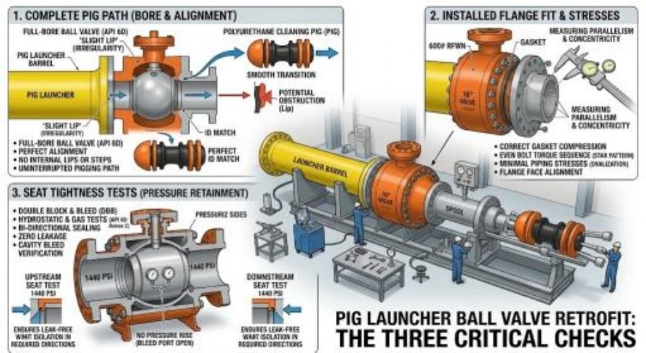
At another station, a closed valve shows a slow pressure rise on the depressurized side. It may be a damaged seat, trapped liquid in the body cavity, or a leaking bypass. Those observations lead to three checks before a pig launcher ball valve retrofit is approved: the complete pig path, the installed flange fit, and seat tightness in the required pressure directions.
Introduction to Pipeline Pigging Systems
What Is Pipeline Pigging?
A pig travels through a pipeline to remove deposits, separate products, inspect the wall, or confirm an internal passage. It is introduced at a launcher and collected at a receiver. The barrel, reducer, mainline valve, kicker line, closures, drains, vents, and instruments must work as a system. A valve that passes normal fluid flow may still obstruct a pig.
The launcher is a pressure vessel and an operating sequence. Before opening its closure, operators isolate, vent, drain, and verify zero pressure. During launch, the mainline valve, kicker path, and differential pressure must agree with the approved sequence.
Importance of Ball Valves in Pigging Operations
A ball valve can provide a straight passage when open and dependable isolation when specified and tested correctly. The closed ball separates the live main from the launcher; the open port must clear the particular pig, its cups, and any instrument package. These ball valve applications demand suitable stem and seat materials for the medium and pressure.
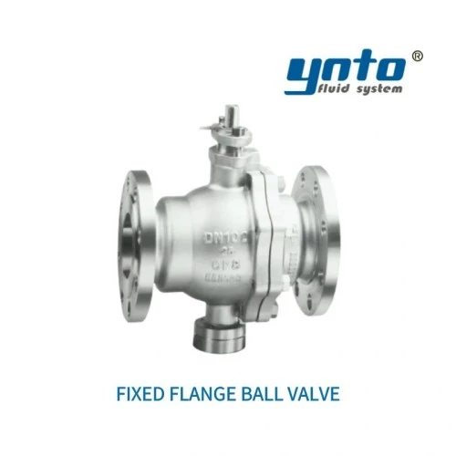
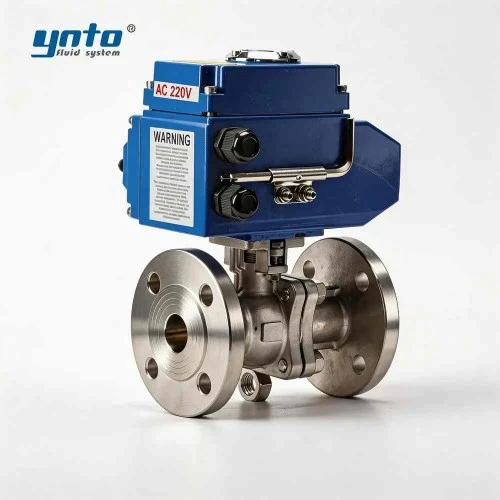
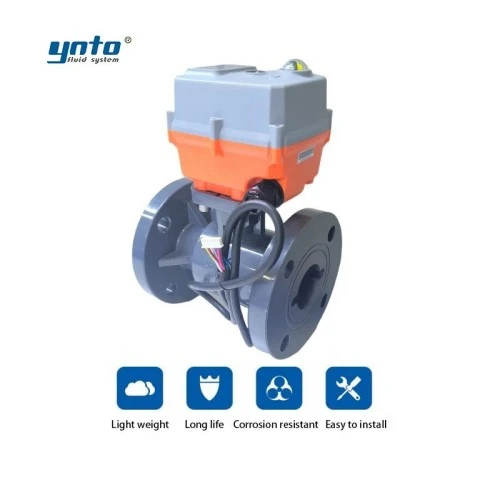
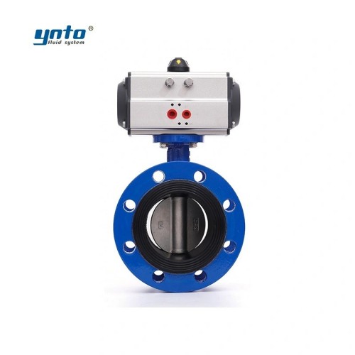
YNTO's fixed flanged ball valve for pipeline service lists both full-diameter and reduced-diameter options, along with manual, pneumatic, electric, and hydraulic drives. That makes it a useful product family to discuss for a retrofit. Specify and verify the full-opening configuration where the pig must pass; the family description alone does not establish piggability of the ordered valve.
Before requesting a 1:1 replacement, compare the old drawing with the pig envelope. Matching nominal pipe size may conceal a special bore, chamfer, or seat-pocket geometry.
Assessing Bore Clearance in Valve Retrofits
Definition and Measurement Techniques
“Full bore” and “full opening” are useful starting descriptions, but the controlling dimension is the smallest unobstructed passage along the assembled pig route. Measure the open ball port, both ends of the body, seats, weld transitions, spool pieces, and any lining or protruding gasket. Check the opening at the valve's actual mechanical stop; an indicator at 90 degrees does not prove that the ball port is concentric with the pipe.
Ask for the pig's maximum operating diameter, articulation, cup wear range, and allowable step or gap. A foam pig may tolerate geometry that an instrumented tool cannot; body length also matters at cavities and short transitions.
During a shutdown, inspect dimensions and use an approved gauge or dummy pig if appropriate. Record the minimum bore and every change in section for procurement and site crews.
Implications of Poor Bore Clearance on Pipeline Integrity
A lip at a flange or a partly opened ball can snag a cup. The pig slows, pressure rises behind it, and a sudden release may drive it into the next fitting at excessive speed. The obstruction can also shed debris into the seats. A minor installation tolerance becomes a shutdown or recovery operation.
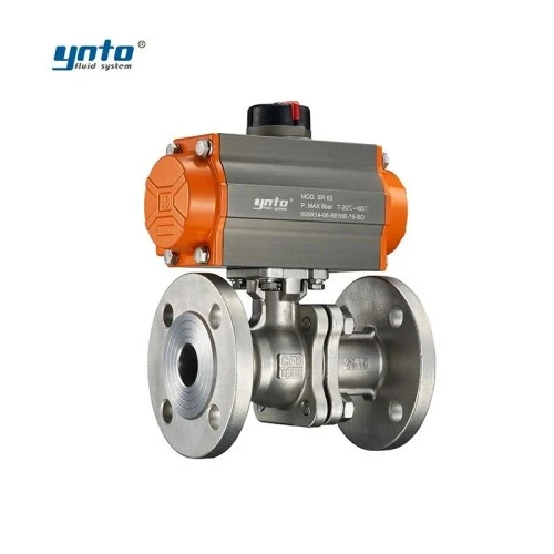
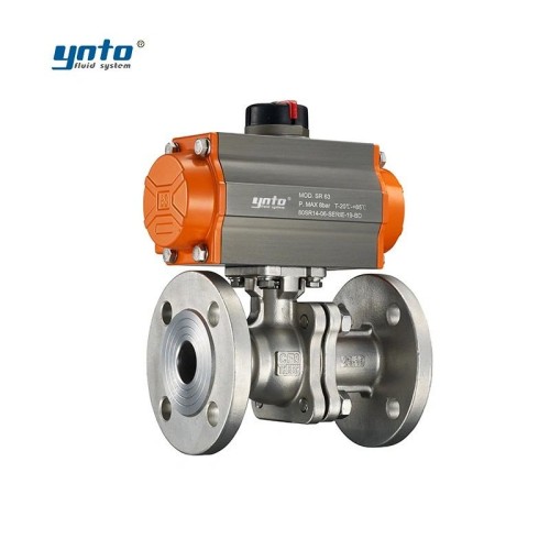
The YNTO pneumatic flanged quarter-turn ball valve describes a body channel aligned with the connecting pipe diameter. That warrants review, not automatic pigging approval. Request a section drawing and exact open-port dimensions for the selected size and trim; compare them with the actual pig envelope.
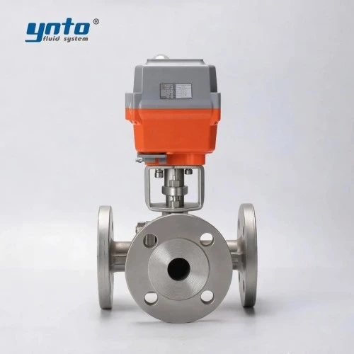
Instrumented pigs need predictable clearance for sensors and joints. A cavity can also let fluid bypass a short pig and alter its speed. Pipeline integrity management links the valve to pig geometry, pressure, velocity, and retrieval; inspect the full route, including reducers and branches.
Engineers also notice that a valve becomes harder to stroke after dirty pigging runs. Solids caught at the seat increase torque; repeated closure crushes particles against the sealing edge, and subsequent isolation tests show leakage. A suitable seat design and flushing or cleaning procedure can reduce that wear, but a larger actuator cannot make a damaged seat tight.
Flange Fit Considerations
Types of Flange Connections Used with Ball Valves
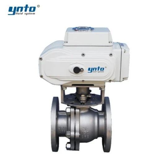
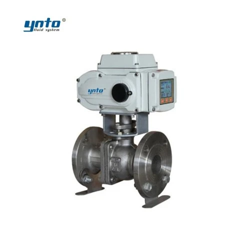
The word “flanged” does not define a connection. Record the flange standard, nominal size, pressure class or PN rating, bolt-circle diameter, number and size of holes, facing, gasket type, and face-to-face dimension. An ASME Class designation cannot be swapped for a PN label by choosing a roughly similar pressure number. Temperature, material, and the governing flange table affect allowable pressure.
Compare old and proposed drawings. A matching bolt circle may conceal a different raised-face height or body length. A compensating spool changes support loads, inspection, and downtime; price that work explicitly.
Ensuring Optimal Flange Fit for Operational Safety
Check whether the launcher and mainline move differently with temperature. If the pipe is pulled into position by flange bolts, bending loads pass into the valve body. This may distort seat alignment, raise operating torque, and produce a leak after several thermal cycles. Support and align the line before tightening bolts using the specified sequence and torque method.
The gasket must tolerate the medium without intruding into the bore or leaving a debris-catching recess. Inspect the internal transition as well as external tightness.
YNTO's ANSI/ASME flanged ball valve cites dimensional and rating references and API 598 pressure testing. Compare it where an ASME-pattern flange is required, then confirm the class, face-to-face length, bore, seat construction, and test records for the ordered version. Its listing does not establish piggability.
Material selection follows the fluid and environment. Carbon or alloy steel may suit the pressure boundary with a suitable corrosion allowance and external coating such as FBE. For chloride-bearing or aggressive streams, 316L or Duplex may be considered after a compatibility and strength review. PTFE, FKM, or other seat and stem-seal materials need pressure, temperature, and chemical checks. A metal seat may withstand heat and abrasive solids better, but its permitted leakage must be specified rather than assumed to match a soft seat.
When the project calls for API 6D pipeline valves, state its edition and the required valve configuration and documentation. ANSI/ASME B16.5 addresses applicable flange geometry and ratings; ASME B16.34 addresses applicable metallic valve ratings and testing. DIN EN 558 or ASME B16.10 may establish face-to-face dimensions, depending on the specified pattern. ISO 5208 and API 598 provide test frameworks where invoked. None of these labels alone demonstrates that a particular pig will pass.
Overview of Valve Control Systems
Key Components of Valve Control in Pig Launching
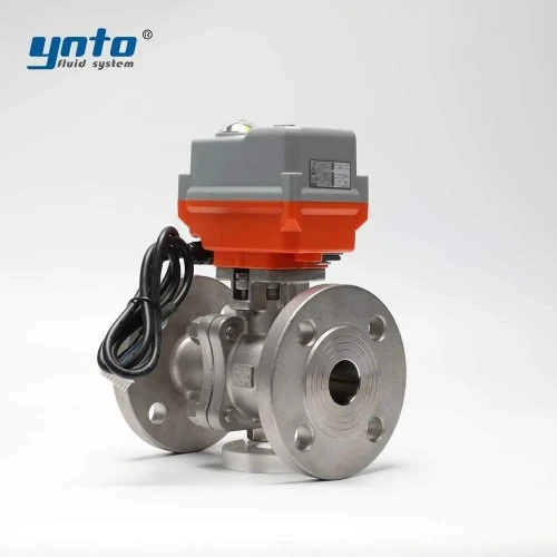
Valve control systems combine the ball valve, actuator, air or power supply, directional control, position feedback, and an operating sequence. The launcher also needs independent pressure indication and isolation verification. A “closed” command is a request; a limit switch confirms actuator travel, while a pressure test checks the pressure boundary. Specify this fluid control equipment as an assembly.
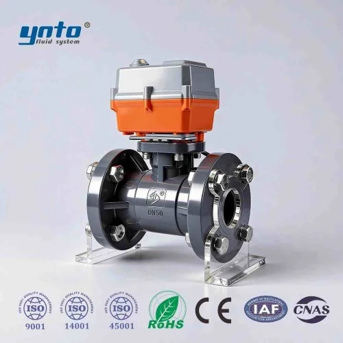
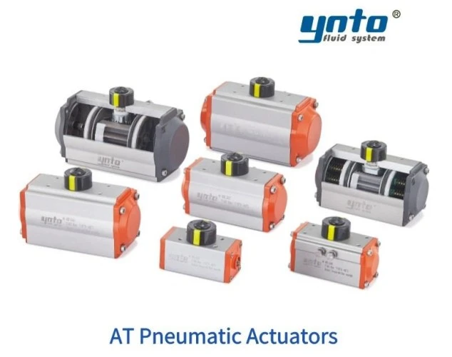
For industrial valve automation, review breakaway torque at maximum differential, minimum air pressure, dirty-seat friction, and stroke time. The AT pneumatic actuator range offers double-acting and spring-return options for evaluation with the valve. Confirm torque curves and fail action: loss of air to a double-acting actuator does not guarantee a safe final position.
A kicker-line valve helps establish differential pressure behind the pig. Include its position in permissive logic without confusing it with mainline isolation. If flow control technology moderates launch speed, test it across expected pig friction and pressure. Too much differential causes violent launch; too little strands the pig.
Automation and Its Role in Enhancing Valve Performance
Automation can make the approved sequence observable: confirm closure and vent status, load the pig, restore pressure, align flow paths, then launch and verify passage. A PLC indication never replaces the local zero-pressure check before opening a closure.
Feedback is diagnostic. A longer command-to-open time can indicate low air pressure, a sticking solenoid, rising torque, or a misadjusted stop. Record both stroke times at commissioning.
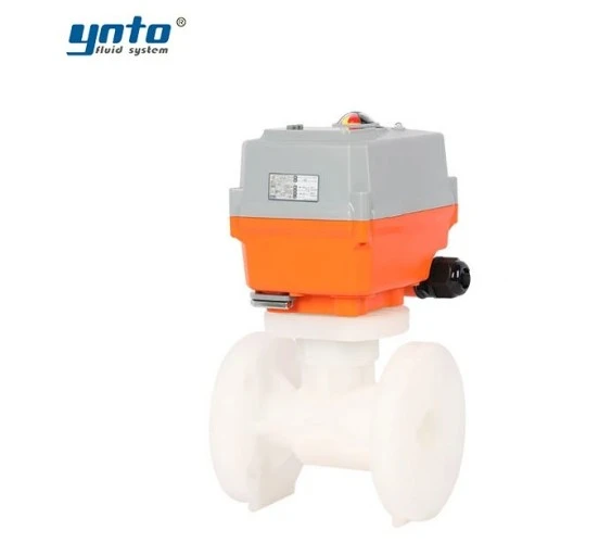
Rapid closure against liquid flow can create surge, while slow closure may conflict with isolation requirements. Size the actuator and pneumatic circuit together. An electric option also needs a verified torque profile and fail response.
Conducting Seat Tests for Valve Reliability
Procedures for Effective Seat Testing
Start with the purchase specification. It should define shell-test and seat-test medium, pressure, duration, test direction, allowable leakage, and any required documentation or witnessing. Factory testing establishes the delivered valve's condition. Field testing after installation checks the assembled boundary and may expose flange or handling damage. The two are complementary, not interchangeable.
During a closed-valve seat test, keep the relevant side at the specified pressure while the opposite side is monitored safely for leakage. If bidirectional shutoff is required, test each direction under the approved procedure. Confirm whether any body-cavity bleed is part of the design; do not assume that two seats plus a drain create a certified double-block-and-bleed arrangement. A trapped cavity must be vented or protected as engineered before heat or pressure can build in it.
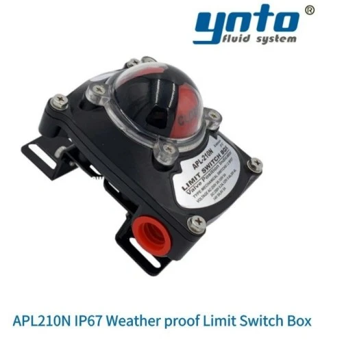
For position feedback, YNTO's APL210N limit switch box can signal actuator open or closed travel. It is helpful for recording the stroke and interlocks, but it cannot measure seat leakage. Close indication, zero pressure at a drain, and a documented seat test answer different questions; all three may be needed before a launcher is opened.
High-pressure gas service deserves particular care because stored energy remains even after a gauge begins falling. Isolate, depressurize, drain, and verify through the prescribed points before breaking a flange or operating the closure. Hot, corrosive, or toxic contents add exposure risks. Follow the plant permit, lockout, gas testing, and personal-protection rules; do not improvise a pressure test from the launcher barrel without the approved test boundary.
Common Issues Identified During Seat Tests
If leakage appears, confirm it is through the seat rather than an open bypass, leaking drain, pressure equalization line, or test fitting. Rising pressure in an isolated launcher can reflect thermal expansion of trapped liquid. Repeatable leakage under a defined test pressure, especially after a dirty run, directs attention to seat damage or debris. Seat tests should be interpreted with the valve's allowable leakage class, not an unspecified promise of “zero leakage.”
Another pattern is acceptable leakage at room temperature followed by a small leak after a hot operating cycle. Temperature changes alter seat loading; an unsuitable soft seat can relax, and the next reversal of differential exposes the gap. If the engineer responds only by increasing actuator torque, stem and seat wear may accelerate. Material selection, seat geometry, and the test temperature must be reviewed together.
Ask the supplier for a drawing of the pressure boundary and open bore, material traceability, flange dimensions, actuator sizing, factory test results, and any API 6D compliance claimed for the exact configuration. For a 1:1 retrofit quotation, add the old valve tag and drawings, pig envelope, design pressure and temperature, media, and required test procedures. That information turns an ordinary ball valve inquiry into a specification that can be checked before the crew reaches the site.
Conclusion: Specify the Complete Pig Path
A successful retrofit does more than fit between two flanges. It presents a verified passage to the actual pig, connects without forcing the pipe, responds predictably to the launcher sequence, and passes the specified seat tests. For the YNTO products discussed here, request configuration-specific drawings and records before calling any valve piggable. The same evidence supports safer operations and a more durable pipeline integrity management program.
- 2026-11-16 08:38:37
- 2026-11-13 09:36:01
- 2026-11-11 15:08:29