

How a Flow Balancing Valve Optimizes Water Supply Systems
- 2026-07-22 11:01:35
- admin
- NO COMMENTS
In a large water-supply network, one often notices that nothing seems broken—yet some zones get too much flow, while others are starved. For example, during a morning peak in a multi-story building, one wing’s taps may sputter under low pressure while another wing gushes excess water. An engineer making rounds in such a system might observe slight pipe vibrations at low flows or hear pumps fluctuate in speed. These are the first clues of an unbalanced system: pressure swings ripple through the plumbing, causing valves to hunt and compensating pumps to cycle more frequently. Such subtle issues rarely cause an immediate flood, but they quietly waste water and energy over time.
In many field operations, the chain of events is predictable. For example, an upstream pressure surge leads to a downstream pressure drop, triggering valve or pump overcompensation. The result is flow oscillation: one branch becomes overfed while another is underfed. Operators may then crank balancing valves or adjust pump speeds to even things out. This friction and constant adjustment wears seals and trims, slowly eroding performance and increasing leakage risk. In short, fluctuating pressures → unstable flows → valve hunting and wear → leaks and wasted water. A well-chosen flow-balancing valve and control strategy break that chain early, stabilizing pressures and flow rates.


Key Components of Flow Balancing Valves
Flow balancing valves come in various types, each suited for different systems. Flow Control Balancing Valves (sometimes called throttle valves) provide a precise pressure drop to fix a branch flow at a set rate. Hydraulic balancing valves often incorporate springs or diaphragms to maintain constant flow despite pressure changes. Thermostatic and pressure-independent valves (common in HVAC) adjust automatically based on temperature or pressure changes. In practice, a system designer might use a manual regulating valve on each branch, or even install automatic balancing valves that self-adjust.
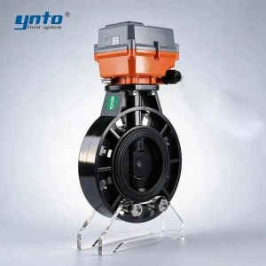
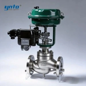
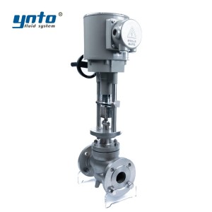
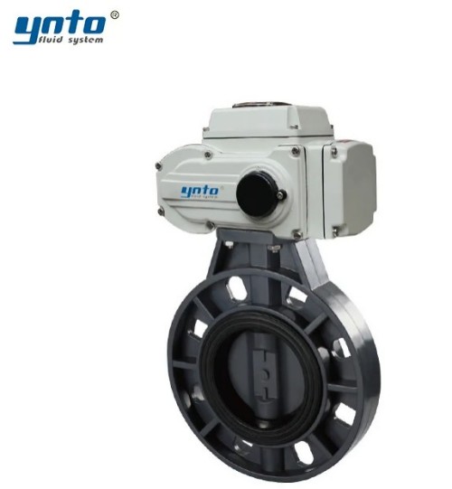
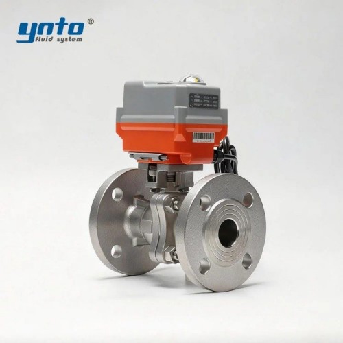
Beyond balancing valves themselves, other hardware is involved. For on/off and shutoff duties, products like an Electric Ball Valve or Electric Butterfly Valve are common. These electrically actuated valves (with 316L stainless bodies and EPDM/PTFE seals) are used to isolate sections or rapidly modulate flow in large lines. For fine-tuning under digital control, an Electric Control Valve can be used. Such valves accept 4–20 mA signals for tight flow regulation and leak-tight shutoff, preventing the overshoot and hunting seen in looser valves. In essence, these control valves feed into the balancing strategy, ensuring the intended flow rates are met once set.
The Role of Flow Rate Calibration
Calibrating and measuring flow is critical for optimal balancing. Engineers use flow meters (magnetic, ultrasonic, or venturi types) and differential pressure gauges to verify actual flow rates in each branch. During commissioning, calibration might involve slightly throttling each branch valve until each zone’s flow matches the design target. If one zone draws more, its balancing valve is nudged closed until flows equalize. This is often done while monitoring with flow measurement devices. Without accurate calibration, one circuit may “rob” flow from another—a common cause of the uneven pressures noted above.
In technical terms, the calibration procedure sets a fixed pressure drop across each balancing valve so that, even as the main supply pressure changes, the branch flow stays constant. For example, an engineer might adjust a valve until 10 L/min flows under normal conditions; after that, even if upstream pressure rises, the valve’s geometry holds that flow steady. According to hydronic best practices, such calibration ensures even distribution of water—which not only conserves water but also keeps temperatures and pressures uniform. Balanced systems avoid the noise and inefficiency of unregulated flow and give all users the water they need.

Pressure Control Solutions
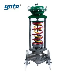
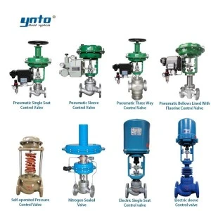
Maintaining appropriate pressure levels is as important as regulating flow. High or fluctuating pressure can overpower balancing valves and lead to water hammer or leaks. In many systems, pressure-reducing valves (PRVs) are installed at key points to limit pressure to safe levels. More advanced setups might use self-contained regulators. For instance, a Self-operated Pressure Control Valve uses the fluid’s own pressure to modulate its spindle, keeping outlet pressure stable without external power. These devices are essentially fail-safe regulators: if an upstream surge occurs, they automatically partially close to hold downstream pressure constant. This prevents the severe flow swings that can overwhelm balancing valves.
On larger water mains or boiler feeds, industrial control valves may be fitted with actuators and linked to pressure transducers. An electric control valve can be programmed via a PLC to respond to pressure sensors. With fast feedback, such valves close just enough to prevent downstream pressure from exceeding setpoints. In normal use, this keeps the supply stable so that balancing valves only handle small variations. In emergency or maintenance conditions, the actuation speed also helps isolate sections quickly. For example, an electric control valve can shut off flow to a leaking branch faster than any manual operator, limiting water loss.

Performance Measurement
No balancing strategy is complete without measurement. Continuous or periodic metering verifies that flows and pressures stay within target ranges. Simple meters (e.g. Magmeters or ultrasonic clamps are installed on representative branches, especially in critical zones like top floors or dead-ends. Trending these readings alerts operators to drift: for example, if a meter shows branch flow slowly dropping (perhaps due to valve wear or clogging), maintenance can be scheduled before comfort is affected.
Best practices include logging sensor data and using controller alarms. Modern flow measurement devices can even integrate with building automation, providing real-time flow and totalized usage. This data allows fine-grained audits of water use and identifies leaks or unauthorized usage. In fact, without flow monitoring, a balancing system is operating blind. According to HVAC guidelines, accurate flow measurement paired with properly selected balancing valves is key to diagnosing and preventing uneven distribution.

Conclusion
Balancing valves and pressure regulators are critical to making a water system efficient and reliable. By holding branch flows to design values and clipping pressure peaks, they prevent the cascading effects of imbalance—from noisy pipes to hidden leaks. Water utilities and building engineers should ensure that these components are selected and installed correctly: 316L stainless steel bodies for corrosion resistance, PTFE/EPDM seals for tight shutoff, and spring or actuator sizing that matches the system’s pressure range. Safety standards (e.g., ANSI/ASME ratings, API and ISO compliance) must be met to handle maximum pressures safely.
Next Steps: Consider an audit of your system’s flow patterns using portable flow meters and loggers. Where imbalances are found, install or adjust balancing valves at key branches. Combine them with reliable electric control valves or self-operated pressure control valves to stabilize pressure, and use flow meters to verify improvements. A properly balanced system uses less energy, reduces pump wear, and saves water—delivering better performance for every user.

- 2026-10-19 08:49:57
- 2026-10-16 10:48:59
- 2026-10-15 14:23:43