

Fail-Safe 3-Way Electric Ball Valves for Data Center Cooling
- 2026-10-15 14:23:43
- admin
- NO COMMENTS
During a cooling-skid changeover, the pump status stays green, but differential pressure begins to fluctuate. A three-way valve hesitates halfway through its travel. The controller asks for more cooling, the actuator moves again, and the supply-temperature trend starts climbing. Engineers watching the sequence need to know whether the problem is insufficient torque, an unsuitable flow characteristic, or the wrong passage opening at the wrong moment.
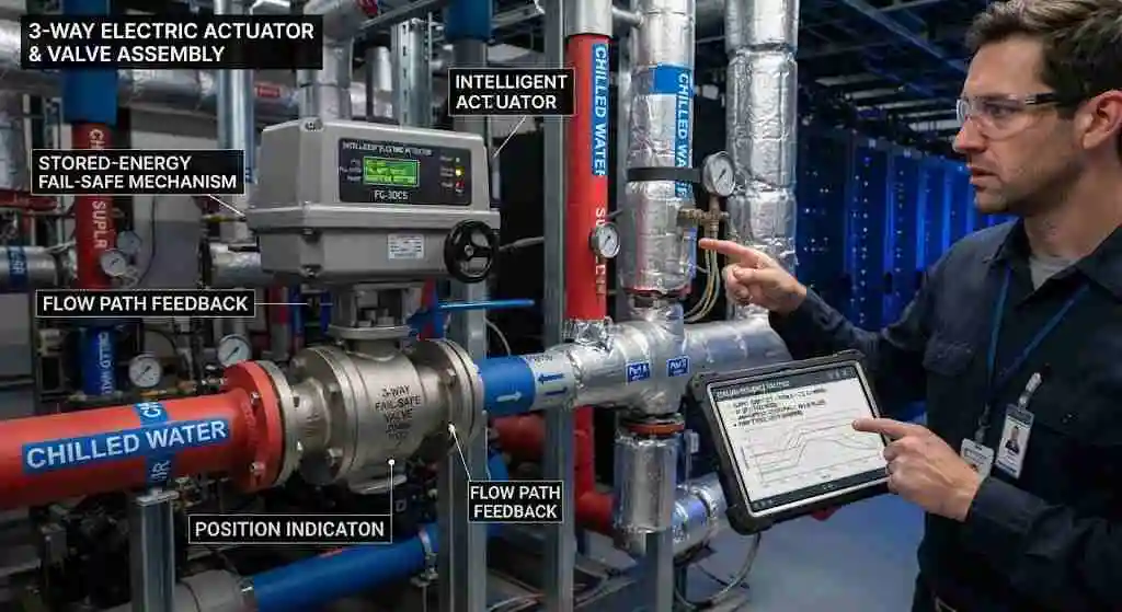
A fail-safe three-way electric ball valve for data center cooling must provide a defined flow path when something fails. Specifying voltage, pipe size, and “fail-open” leaves too much unresolved. The valve, actuator, stored-energy mechanism, feedback, and cooling sequence need to work as one assembly.
How to Specify a Fail-Safe Three-Way Electric Ball Valve for Data Center Cooling
The Role of Cooling Systems in Data Center Performance
1. Understanding the Thermal Management Needs
Data center thermal management begins with a heat balance and an operating envelope. Establish the required heat removal, coolant supply and return temperatures, minimum flow, and allowable pressure loss. A valve on the facility-water side of a cooling distribution unit faces different cleanliness and coolant requirements from a valve on the technology-cooling loop serving cold plates.
Identify the hydraulic function before selecting hardware. Mixing combines two compatible streams into one outlet. Diverting sends one inlet stream toward different branches. A three-way valve may regulate a heat-exchanger bypass, but its port geometry and permitted flow directions must support that exact duty.
Ask the cooling designer how long the load can tolerate reduced heat removal during transfer. That interval, together with standby-equipment starting time, sets the available valve-response budget. A fast actuator offers little benefit if the receiving branch is still unavailable when the valve reaches it.
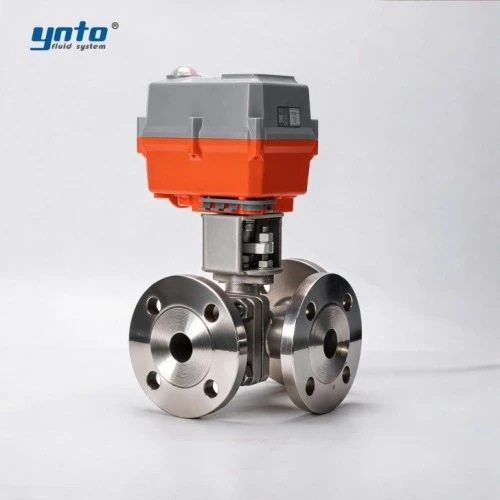
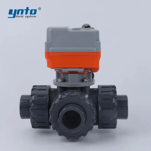
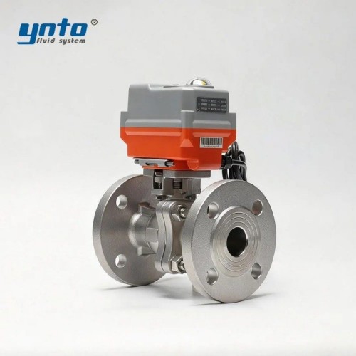
YNTO’s three-way flanged electric ball valve with power-off reset options provides a starting point for discussing mixing, diversion, and automated cooling applications. Its published options include L-port and T-port configurations. Request the specific assembly drawing, flow curves, and return mechanism rather than treating every configuration as interchangeable.
2. Challenges Faced in HVAC Control Systems
HVAC control systems must remain stable as pumps change speed and branches enter or leave service. An oversized valve can deliver a large flow change from a small movement near its seat. The controller repeatedly corrects the resulting temperature deviation, increasing actuator cycling and making low-load operation uneven.
The opening sequence matters just as much. A passage that closes before the alternative opens can briefly restrict circulation; an overlapping passage can connect branches that should remain separate. Review intermediate positions, not only the two end stops, when integrating the valve into data center infrastructure.
Characteristics of Fail-Safe Valves
1. What Makes a Valve “Fail-Safe”?
Fail-safe describes the assembly’s response to a specified failure. A spring-return actuator stores mechanical energy. An electronic return system uses an identified energy source, such as a capacitor or battery, to drive the valve after normal power disappears. An ordinary motorized actuator may simply remain where it stopped.
For a three-way assembly, define safety by port connection. On an illustrative drawing, the common port might connect to the cooling branch after power loss while the bypass closes. Another installation may require a different route. Port letters vary between manufacturers, so the approved drawing must identify the common connection, rotation direction, and final passage.
Specify separate responses to power failure, lost control signal, communication timeout, and invalid temperature feedback. A power-off return feature does not automatically handle all four. State the return time under the maximum specified differential pressure, along with any delay before movement begins.
2. Importance of Reliability in Data Center Cooling
The preferred failure position must reflect available cooling capacity and pump behavior. Opening a route through an unavailable heat exchanger will not preserve cooling. Likewise, diverting flow into a bypass may maintain circulation while allowing coolant temperature to rise. The plant sequence determines which outcome is acceptable and for how long.
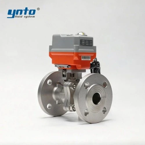
Leak containment may require separate isolation. YNTO’s flanged electric isolation ball valve with power-failure reset is a candidate for an appropriately engineered branch-isolation duty. Confirm its reset direction, leakage acceptance, and closing time against the leak-response sequence. A three-way routing valve should not be assumed to isolate every connected branch.
Also examine shared failure points. If redundant cooling branches depend on one actuator, one power module, or one common valve body, that component remains a potential interruption point. A three-way valve does not itself establish cooling redundancy, and its return function cannot restart an unpowered pump.
Stored energy also cannot guarantee movement through a mechanical seizure. Specify how a failed return is detected and what the supervisory system does next. The response may require another available cooling path or an approved reduction in computing load, depending on the facility design.
Benefits of Three-Way Electric Ball Valves
1. Smart Valve Technology Overview
Useful smart valve technology connects commanded position, measured position, and the actual cooling response. During commissioning, a rising command with little shaft movement suggests friction, insufficient torque, or a drive problem. Normal movement without the expected temperature response points toward flow, sensor placement, or the hydraulic arrangement.
Feedback needs equal scrutiny. A position signal can show where the actuator is, but it does not prove coolant flow or seat tightness. Correlate position with flow, differential pressure, and temperature. Where available, motor-current and travel-time trends can help identify developing resistance before a valve stalls during a changeover.
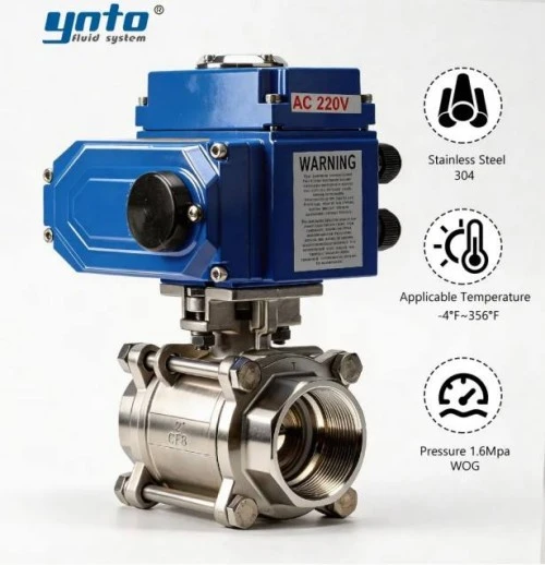
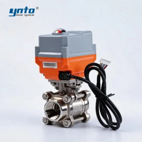
For compact threaded assemblies, YNTO’s RS485-compatible three-way electric regulating ball valve offers a relevant configuration to evaluate. Specify the supported protocol, register map, analog options, and timeout behavior for the ordered version. RS485 describes the electrical communication interface; it does not by itself guarantee compatibility with the building management system.
Place the control-temperature sensor where it represents the intended mixed supply, with adequate mixing and a response suitable for the loop. A delayed measurement can make the controller continue moving after enough cooling has already been admitted. The resulting overshoot encourages further corrections and makes a healthy valve appear unstable.
2. Impact on Cooling System Efficiency
A well-selected three-way valve can manage bypass or mixing duties with fewer separately actuated components. That can simplify coordination and reduce installation space. The gain depends on maintaining the intended flow distribution through the entire operating range.
Three-way control does not automatically improve cooling system efficiency. Unnecessary bypass flow can keep pumping demand high and lower the temperature difference across the plant. In systems designed for variable flow, compare the proposed three-way arrangement with the existing hydraulic strategy before promising energy savings.
Size each operating path using its published Kv or Cv. As a simplified water-duty example, 12 cubic meters per hour with 0.25 bar allocated to the valve corresponds to Kv 24. This is an initial calculation, not a final selection. Glycol concentration, viscosity, temperature, and the manufacturer’s sizing method can change the requirement.
Ask for both branch characteristics and their behavior during transition. Equal nominal connection sizes do not guarantee equal capacities. Check minimum-load controllability and valve authority, the valve’s share of pressure loss in the controlled circuit. Selecting only for low full-open resistance can leave too little useful control over flow.
Selecting the Right Valve: Automated Valve Solutions
1. Valve Actuation Methods
Choose valve actuation methods around the operating sequence. On/off service needs dependable routing between defined positions. Modulating service needs adequate positioning resolution, repeatability, duty rating, and response without excessive hunting. A fast switching actuator is not automatically suitable for continuous temperature regulation.
YNTO’s electric actuator range with switching and modulating options allows these requirements to be discussed separately. Confirm the exact control version, supply voltage, feedback, permitted cycling, and available torque. Order the fail-safe function explicitly; general actuator features do not establish the return capability of a completed valve package.
Torque selection must cover breakaway, running, and seating requirements at the specified differential pressure and temperature. Deposits or deteriorating seals increase friction; the actuator then takes longer to move, extending the cooling transition and potentially triggering a temperature alarm. Additional torque cannot correct a damaged seat or an unsuitable valve design.
For electronic return, obtain charging time, readiness indication, energy-storage service requirements, and performance after repeated power interruptions. For spring return, verify available torque throughout the return stroke. In either case, assess operating speed against hydraulic surge risk. An abrupt flow change can create a pressure transient that loads joints and vulnerable cooling components.
2. Compatibility with Thermal Management Systems
Review the complete coolant formulation, including glycol, inhibitors, and cleaning chemicals. 316L may suit many treated-water applications, but it is not immune to chloride attack. PTFE seats offer useful chemical resistance; EPDM and FKM seals require compound-specific approval for the actual fluid and temperature. A material name alone is insufficient evidence of compatibility.
Repeated thermal cycling can reduce an unsuitable elastomer’s sealing resilience. Small leaks then appear at stems or joints, leading to coolant loss and moisture near electrical equipment. Include minimum and maximum operating temperatures, cleaning conditions, and credible pressure excursions in the specification rather than providing only normal room-temperature duty.
Preserve hydraulic separation between facility and technology loops. A mixing valve must not bridge circuits with different coolant chemistry or water-quality requirements. For chilled services, maintain insulation and vapor barriers around the valve while protecting actuator access. An enclosure rating alone does not solve condensation inside an incorrectly installed electrical housing.
Confirm the permitted water-quality range with the equipment and coolant suppliers. Corrosion products can damage sealing surfaces or collect in narrow passages, increasing resistance and disturbing flow distribution. Material selection and ongoing fluid maintenance therefore belong in the same reliability review.
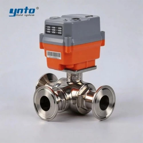
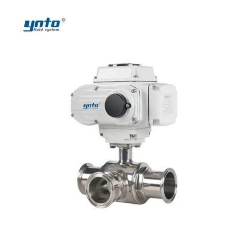
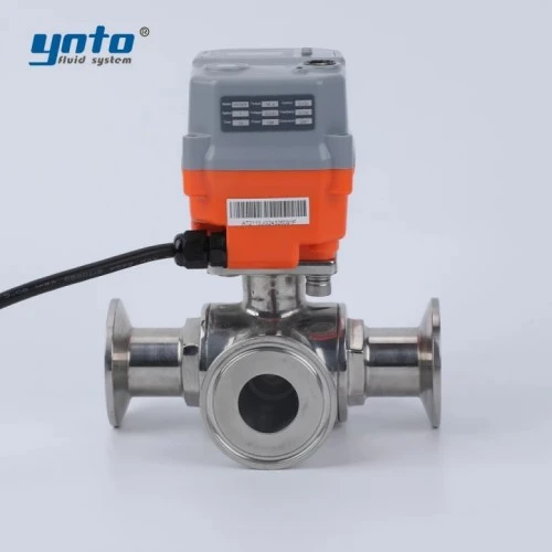
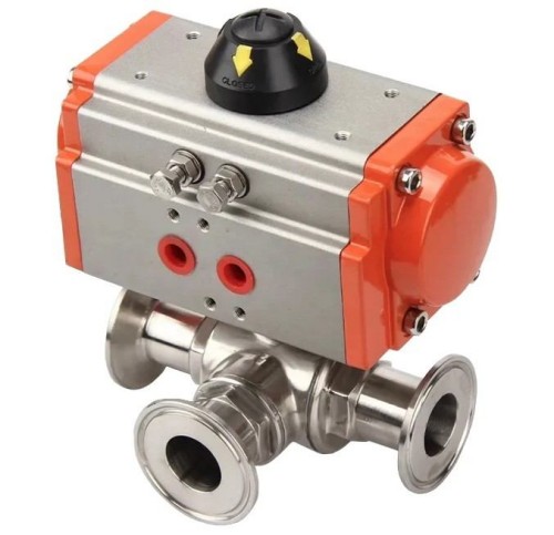
Where the skid uses compatible clamp connections, YNTO’s 316 stainless steel three-way electric clamp ball valve offers another connection format to assess. Verify the actual alloy, gasket, clamp dimensions, pressure rating, and service access. A clamp connection intended for convenient dismantling still needs mechanical restraint and an approved installation procedure.
3. Evaluating Automated Valve Solutions
Compare automated valve solutions using a common specification and documented acceptance criteria. For applicable metal valves, ANSI/ASME B16.34 addresses pressure-temperature ratings, materials, and testing. API 598 provides valve inspection and testing requirements. ISO 5211 addresses part-turn actuator attachments, while DIN EN 1092-1 addresses PN-designated steel flanges. None independently proves that the assembled valve will perform the required cooling failure sequence.
Request shell and seat-test records with defined test pressures, duration, medium, and leakage limits. State which passages must seal and in which pressure directions. Then verify the complete valve-actuator assembly under representative hydraulic conditions, including power removal, signal loss, and recovery. Observing a motor turn on a workbench is insufficient.
During site commissioning, check that physical port markings match the piping drawing and displayed operating state. Trend flow, differential pressure, supply temperature, and travel time during approved changeover tests. Confirm that communications recovery does not unexpectedly override a protective state and that stored-energy readiness is restored before the next required demand.
Record the configuration delivered with each valve tag, including firmware where applicable. Retain the approved settings and test results so a future actuator replacement can reproduce the intended behavior.
Maintenance planning belongs in the specification. Provide access for inspection and actuator removal, identify replacement seals, and agree inspection intervals. Before opening the system, follow plant isolation, electrical lockout, depressurization, and coolant-handling procedures. Hot water, trapped pressure, and corrosive cleaning residues can remain hazardous after the controller reports the valve closed.
Also record whether manual override inhibits automatic return and how technicians restore service afterward. A valve left in a service setting can appear available on the control screen while its protective function remains disabled. Make that status visible and include restoration checks in the maintenance procedure before handing the equipment back to operations.
For a useful YNTO quotation, submit the piping diagram, coolant specification, flow range, pressure and temperature limits, connection dimensions, required port positions, fail-safe time, and control interface. Request an identified, fully documented assembly, approved drawings, and a witnessed test proposal. These details turn a generic three-way valve inquiry into a purchase specification that supports dependable cooling.
- 2026-10-15 14:23:43
- 2026-10-12 15:56:29

- 2025-11-10 12:00:00