

Steam Pressure Regulator Sizing for Boiler Retrofits
- 2026-10-23 10:30:14
- admin
- NO COMMENTS
The boiler header holds pressure, yet the gauge beyond an old reducing station wavers each time a process heater opens. A faint hiss comes from the bonnet. At low demand, the plug chatters; at the morning peak, downstream pressure falls below the set point. Another DN50 valve looks like an easy replacement until someone asks whether it will pass the peak steam load.
That question should come before the purchase order. A retrofit must fit the pipework, but a mechanical fit is only half of a true replacement. The other half is stable pressure at minimum, normal, and maximum flow. An oversized regulator may hunt; an undersized one may starve the plant when boiler pressure is lowest.
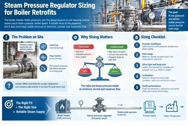
Sizing a Self-Operated Steam Pressure Regulator for Boiler Line Retrofits
Overview of Steam Pressure Regulators
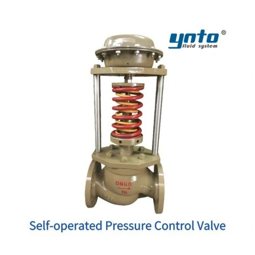
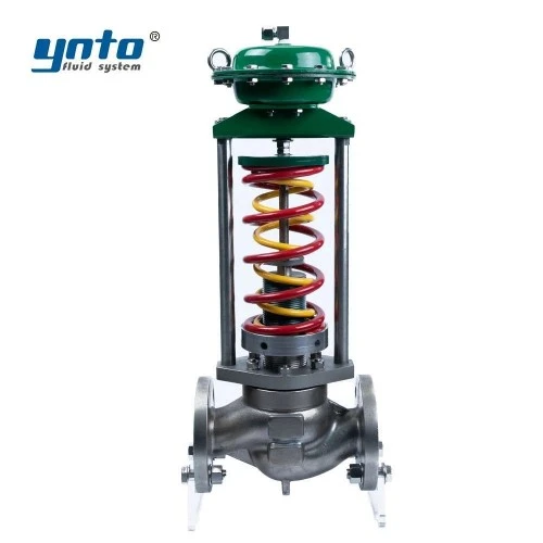
A self-operated pressure-reducing regulator uses energy from the steam system itself to move its valve plug. For downstream-pressure control, the sensed outlet pressure works against a spring or pilot setting: rising outlet pressure tends to close the valve, and falling pressure opens it. It needs no motor power or instrument-air supply. The device is a modulating pressure controller, not an independent safety relief valve or a positive isolation valve.
That distinction matters when reviewing old drawings across pressure reducing stations. Some self-operated valves maintain upstream pressure instead of reducing downstream pressure. YNTO's self-operated pressure control valve is offered in downstream-regulating Type B and upstream-regulating Type K arrangements. A boiler letdown station normally calls for Type B, but the selected spring range, trim, temperature limit, and leakage specification still need confirmation.
If a failed regulator could expose a lower-rated header or heat exchanger to full boiler pressure, the station needs a properly engineered protective device. No claim about the regulator's normal control accuracy can replace that overpressure analysis.
Factors Influencing Valve Sizing
Upstream Pressure
Engineers often find the design boiler pressure prominent and the minimum pressure at the regulator inlet missing. Account for upstream pipe friction, strainers, separators, and station losses at peak demand. Use the lowest credible inlet pressure for capacity, then check the maximum for body rating, shutoff differential, noise, and failure scenarios.
Consider an illustrative station receiving 12 bar(g) normally but 9 bar(g) at the morning peak. With a 4 bar(g) outlet target, sizing from 12 bar(g) alone can make a marginal regulator look adequate. Capacity changes just when demand rises; downstream pressure sags, heating cycles lengthen, and operators may incorrectly increase the spring setting.
Steam calculations must distinguish gauge from absolute pressure. A rough critical-flow screening check uses absolute pressures, not 12 and 4 as bare numbers; actual choked-flow behavior depends on the regulator's geometry and steam state. Send the complete operating envelope to the manufacturer for a compressible-flow calculation instead of extrapolating a water-flow Cv chart.
Downstream Requirements
The relevant outlet value is the pressure required at the process connection under load, not merely at the regulator gauge. Account for pressure loss through the downstream header, any control valve, and the branch to the farthest user. Confirm the lowest permissible process pressure and the highest safe pressure, including the maximum allowable working pressure of the protected equipment.
At no flow, a direct-acting regulator may settle at a different outlet pressure than at full flow. This droop, or proportional offset, becomes a problem when the process band is narrower than the regulator can hold. Seat leakage, damaged sensing lines, or the wrong spring range may worsen pressure creep. Coordinate the safety-valve setting with normal control behavior and the downstream design limit.
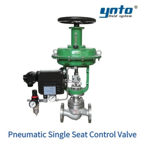
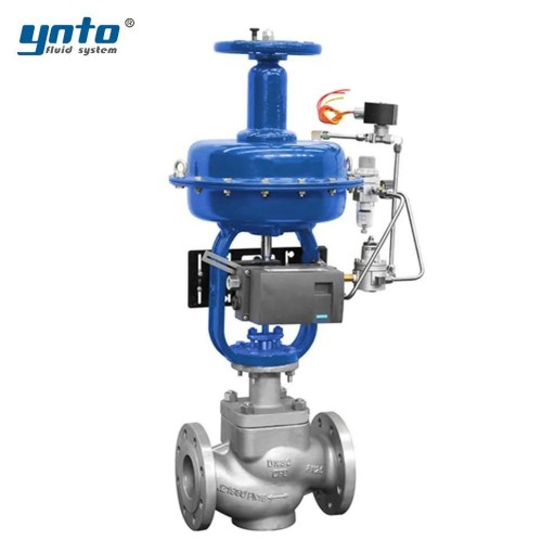
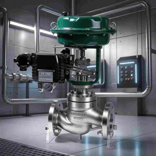
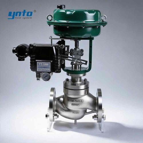
For a one-for-one replacement, record the old unit's setting and pressure trend at idle and full production. Ask YNTO for the proposed setting range, expected pressure variation across those flows, maximum differential, and shutoff leakage. If the required control band is tighter, compare a pneumatic single-seat control valve as a powered-loop alternative, not as a direct-acting substitute.
Flow Characteristics
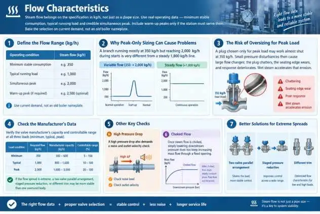
Steam flow belongs on the specification in kg/h, not just as a pipe size. Record minimum stable consumption, typical running load, and credible simultaneous peak. Include warm-up peaks only if the station must serve them. Use current demand rather than an old boiler nameplate.
For example, a branch running mostly at 350 kg/h but reaching 2,000 kg/h during starts differs from a steady 1,800 kg/h line. A plug chosen solely for peak load may work almost shut at 350 kg/h. Small pressure disturbances then cause large flow changes; the plug chatters, the seating edge wears, and response deteriorates. Wet steam accelerates that erosion.
Check the manufacturer's capacity and controllable range at all three loads. A two-valve parallel arrangement, staged pressure reduction, or different trim may be more stable than one oversized body when the flow spread is extreme. High pressure drop also demands a noise and outlet-velocity check. Once steam flow is choked, simply lowering downstream pressure does not keep increasing mass flow through a fixed opening.
Valve Actuator Types for Pressure Control Devices
Comparison of Pneumatic and Electric Actuators
The self-operated unit has its own spring, diaphragm, piston, or pilot mechanism. Pneumatic and electric actuators are alternatives for a controlled valve, not add-ons that make a self-operated regulator more self-operated. Pneumatic control valves use instrument air, a pressure transmitter or controller, and often a positioner. An electric loop uses a motorized actuator and electrical control. Either may be justified if the plant needs remote set-point changes, alarms, or tighter interaction with process automation.
For a rapidly varying steam load, a pneumatic loop may be worth the added complexity. Verify trim, available air, closing force against maximum differential pressure, fail position, and steam temperature. A control signal does not guarantee that the actuator can close against the worst differential.
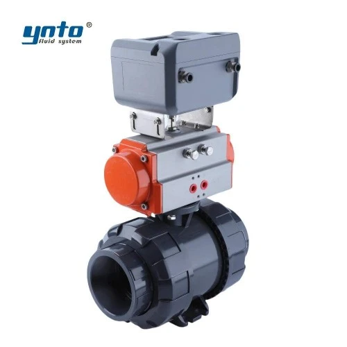
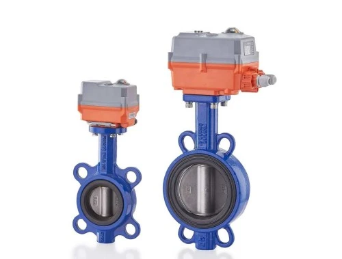
An electric valve package can simplify integration where reliable power and a 4–20 mA control system already exist. Its available thrust, speed, and failure behavior still need checking against the station duty.
Selecting the Right Actuator
For engineers working on site, the decision begins with the process response, not a preference for electronics. If a simple branch has moderate, predictable demand and no requirement for remote adjustment, the self-operated solution often avoids extra power, cabling, and instrument-air maintenance. Where several heat users switch in seconds, compare pressure recovery, acceptable droop, and maintenance resources before choosing a pilot-operated, pneumatic, or electric system.
Ask what happens on power loss, air loss, impulse-line failure, and a stuck plug. A spring-return pneumatic actuator may move to a defined fail position; an electric unit may remain in place unless equipped otherwise. Neither outcome follows from the product family name. YNTO's electric single-seat control valve can be considered for modulating service, but its stated small-differential suitability requires a specific check against the boiler station's pressure drop. Commission the selected failure action against the plant's safety philosophy.
Integration with Existing Systems
Compatibility Concerns
“1:1 replacement” means checking face-to-face length, flange drilling and facing, pressure class, flow direction, clearance, support loading, and sensing-line connection. Compare as-found and proposed drawings before cutting pipe. DN50 PN40 alone does not tell you whether the mating flange is ASME Class 300 or a PN-rated DIN pattern. Gaskets, bolts, and hot-service pressure derating need separate checks.
Many retrofit failures begin upstream of the new regulator. Condensate forms in a cool, uninsulated section; slugs of wet steam strike the seat; the damaged surface starts passing steam even when demand is low. A correctly sized separator, drained strainer, steam trap, and sensible warm-up procedure can protect the trim. The pressure-sensing takeoff should follow the manufacturer's required distance and orientation, away from a turbulent elbow or nearby valve; a sensing line filled with debris will delay response.
Where a station needs positive shutoff for maintenance, specify a separate isolation valve. Confirm its steam-temperature limit, pressure class, failure position, and leakage requirement. A shutoff ball valve should not be substituted for a continuously throttling pressure regulator.
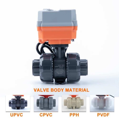
Materials deserve the same application-specific review. Carbon steel or alloy steel can be appropriate for clean boiler steam at the design pressure and temperature; 316L may help where condensate chemistry or cleaning exposure justifies it. Duplex or Super Duplex is not an automatic upgrade for hot steam and needs a reasoned corrosion and temperature assessment. PTFE, EPDM, and FKM are not interchangeable: check the exact temperature, steam-aging behavior, and location of each elastomer or polymer. An FBE external coating may help with ambient corrosion but cannot protect an eroding seat inside the valve.

ANSI/ASME B16.34 can inform applicable valve pressure–temperature ratings, while ASME B16.5 and DIN EN 1092-1 govern different flange families relevant to mechanical fit. API 598 may be specified for applicable isolation-valve inspection and testing; ISO 5208 addresses pressure testing of metallic industrial valves where agreed. These are distinct scopes, not four interchangeable certificates for a self-operated regulator. Specify the actual regulator pressure-boundary test, seat-leakage acceptance, and functional set-point test in the purchase documents, alongside any governing boiler and piping code.
Impact on Thermal Energy Management
An outlet pressure that repeatedly overshoots the process need can increase unwanted heat input and steam leakage through weak traps or worn seats. Pressure that falls too low can delay batches or leave a heat exchanger unable to meet duty. Either symptom distorts thermal energy management: the boiler may be blamed for a distribution problem, while operators compensate with a higher header set point.
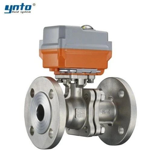
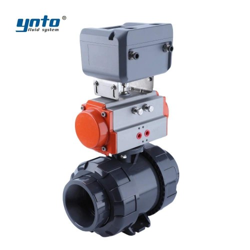
For planned shutdowns, a suitably rated flanged electric ball valve for steam isolation can be evaluated separately from the regulator. Confirm the selected seat's temperature rating and the required failure action before including it in the station design.
Reducing pressure at the right location supports the needed steam temperature, but no regulator guarantees a fixed energy-saving percentage. Insulation, traps, condensate return, boiler control, and operating hours determine the result. Compare baseline and post-installation data at similar production loads.
Performance Evaluation
Monitoring Steam Flow Measurement
Before removal, record inlet and outlet pressures during startup, steady production, and low load. Trend steam flow measurement alongside them. Hourly totals can conceal a capacity shortfall; a gauge snapshot may miss hunting. Confirm mass-flow reporting, density compensation, and meter location relative to pressure reduction.
After installation, increase load progressively. Observe pressure at the remote process user as well as immediately downstream of the valve. Listen for high-frequency hiss and inspect condensate discharge. If the outlet pressure oscillates only at very low load, review selected trim and sensing-line routing before altering the spring. If it droops only at the peak, recheck inlet pressure, strainer differential, steam quality, and verified capacity.
Enhancing Steam System Efficiency
A useful acceptance test covers stable control at minimum, normal, and maximum demand; steady downstream pressure after a load step; no persistent external leakage; and safe behavior when a protection device is tested under the site's procedure. Preserve the as-left spring setting, pressure traces, flow data, and test records. These become the baseline for maintenance rather than another undocumented valve swap.
Safety governs the work. Isolate and lock out the steam line, verify zero pressure, drain condensate, allow for high surface temperatures, and keep personnel clear of possible discharge paths. Confirm that a bypass cannot silently defeat pressure protection; its valves and operating procedure need control. Steam leaks can burn people before a large plume is visible, while a failed regulator can expose lower-rated equipment to boiler pressure.
Final Thoughts
Importance of Proper Sizing
A replacement regulator should match more than an old tag and bolt pattern. Give YNTO the existing make, model, drawings, connections, failure symptoms, downstream set point, minimum/normal/peak kg/h, inlet-pressure range, steam quality, and downstream pressure limit. Request a like-for-like dimensional comparison and a separate sizing calculation. That makes the quotation and retrofit easier to assess.
Future Trends in Pressure Regulation
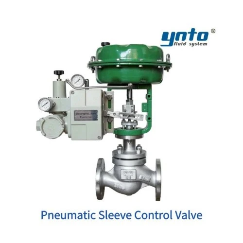
Where a powered loop is justified, a pneumatic sleeve control valve provides another YNTO comparison point for steam and feedwater duties. Request pressure-drop, noise, trim, material, and actuator calculations for the selected configuration. It is an option when the control requirement has changed, not an upgrade automatically required by a self-operated retrofit.
More plants now trend inlet pressure, outlet pressure, and flow to catch drift before it becomes a shutdown. The underlying choice remains practical: a well-sized self-operated regulator may be the simplest pressure control device for a stable duty; an instrumented pneumatic or electric loop earns its complexity when the process needs it. The best result is a station whose behavior is documented at the flows the plant actually runs.
- 2026-10-23 10:30:14
- 2026-10-21 10:41:51
- 2026-10-19 08:49:57